
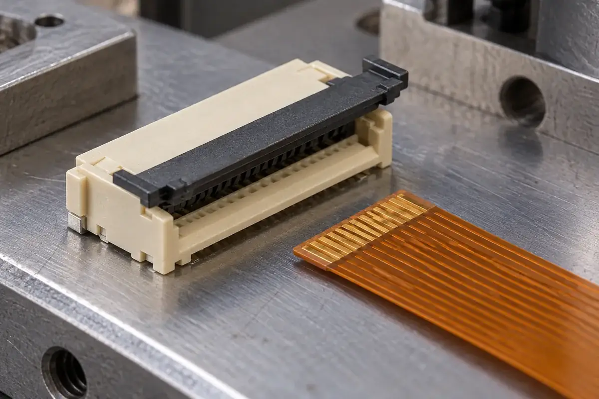
An actuator can look closed because its outside edge aligns with the housing, yet its latch may not have reached the intended retaining surface. It can also engage a latch before the mechanism reaches its proper working state. Travel, final position and engagement are related conditions, but combining them into one visual check makes incomplete closure difficult to diagnose.
The review should follow the moving part from its insertion-ready state through the approach to closure and into retention. At each point, ask which surface guides, which surface stops and which surface resists reversal. This sequence gives a useful framework for evaluating molded hooks, side rails, pivots and housing shoulders without assuming that one audible or tactile event proves everything.
Product design illustrations accompany the molded-component engineering explanations below.
Define the useful travel before defining the latch
The open state must provide the clearance required by the selected cable and mechanism. The closed state must establish the intended working relationship. The motion between them is not merely spare clearance: it may progressively engage a cam, pressure face or guide. Reducing the distance can change that sequence even when the exterior part still appears to fit.
For a slider, compare the travel at both ends. If one end advances first, the frame can rotate slightly in its guides and contact a latch ramp at an unintended angle. The resulting resistance may feel like normal closure. Review rail alignment and the operating method before increasing force or enlarging the latch opening.
For a flip actuator, the equivalent question is whether both ends follow the intended rotational relationship. Unequal support or a bowed bar can cause one latch to approach its shoulder before the other. An overall closed height measured at the center may not reveal the difference. Inspect the relevant end conditions as well as the external silhouette.
Amphenol's OPU series information distinguishes cable pre-holding from the action of its sliding actuator. This is a useful product-specific example of why initial cable retention and final actuator locking should not be treated as identical states.
Distinguish approach clearance from retaining overlap
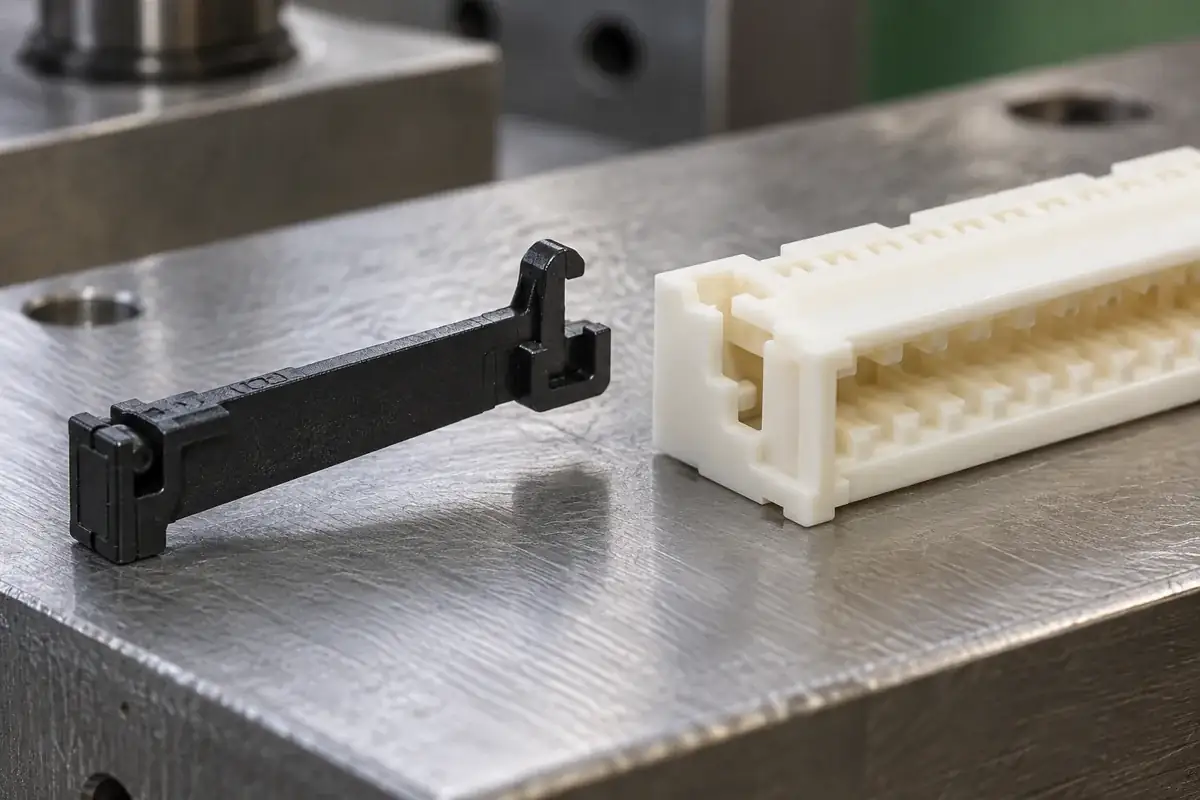
A latch often needs clearance while approaching its mating feature and sufficient overlap after engagement. Increasing clearance everywhere may make closing easier while weakening retention. Increasing overlap may strengthen the geometric interlock while demanding more temporary deformation. The design has to balance these states using the actual material and feature shape rather than maximizing either one independently.
The retaining face and approach face should be identified separately. A rounded approach may help a feature pass its counterpart, while rounding the retaining face can change resistance to reversal. Tool finishing or deburring that treats both edges alike can therefore alter the mechanism. The drawing should communicate where an edge is functional and what condition is permitted there.
Latch roots can be sensitive to local wall transitions and the direction of bending. A broad root is not automatically useful if it forces deformation into a thinner adjacent section. Trace the compliant region and its support. If the design expects the housing to deflect rather than the actuator, that expectation belongs in the assembly review and validation plan.
A stop reached too early can prevent full latch engagement. A stop reached too late can allow unnecessary loading after engagement. The pivot and end-stop discussion shows why these features should be coordinated. The latch should not become an accidental travel stop simply because the intended stop is misplaced or ineffective.
Investigate incomplete engagement in a controlled order
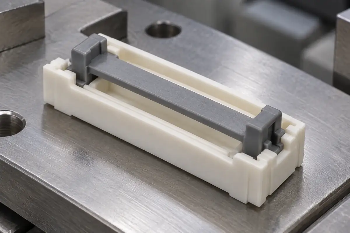
First confirm cable compatibility, orientation and seating. A thick or misplaced cable can prevent the mechanism reaching its intended closed state even when the latch features are correct. The insertion-depth review provides the preceding check. Correcting a latch to accommodate an incorrectly seated cable would conceal the original problem.
Next examine the bare plastic interfaces for flash, local deformation and feature damage. These conditions may be small relative to the overall part but large relative to latch clearance. Inspect the functional edges under suitable lighting and magnification. An acceptable exterior finish does not demonstrate that a hidden hook or recess is complete.
Then compare free-state geometry with the assembled state. A fixture can spread housing walls or hold a slider square while the delivered assembly does neither. If engagement changes when support is removed, the fixture has become part of the mechanism. Either justify that support as representative or revise the check so it exposes the true condition.
Finally, record the point in travel where resistance or asymmetry appears. Early resistance suggests a different investigation from a failure at the retaining shoulder. Observing the sequence with identified samples creates a causal path for measurement. Repeatedly cycling an unexplained tight assembly may damage it and erase evidence of the original interference.
Choose acceptance evidence for the condition being claimed
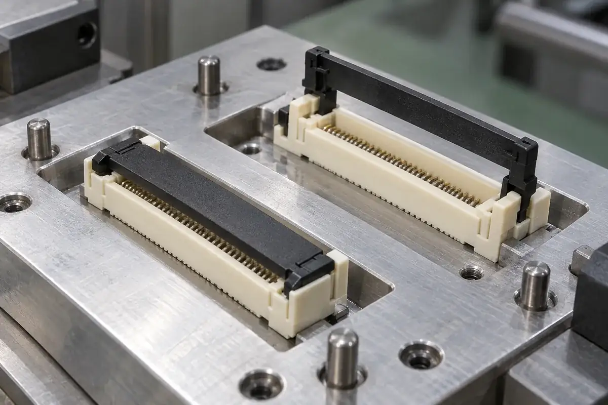
A dimensional report can establish hook location, shoulder position and guide geometry. A controlled assembly trial can establish that identified parts reach a defined state under an agreed method. A retention or durability test addresses a further question and requires its own setup and criteria. Avoid treating one of these records as automatic proof of the others.
Interchangeability also deserves explicit attention. A matched actuator and housing pair can operate well while combinations from different cavities do not. If interchangeability is required, the sampling plan should cross the relevant component sources and revisions. The exercise should be designed around the possible dimensional combinations rather than selecting only the smoothest pair for demonstration.
Closure feedback can aid assembly, but it should be validated against actual engagement. Sound, appearance and tactile response vary with support, materials and surrounding structure. A clear geometric indicator may be more useful than an assumed click, yet it too must correspond to the retaining condition rather than merely the actuator's outer position.
For custom FPC and FFC molded components, define travel states, working surfaces and acceptance alongside the plastic drawing. The wider injection molding review can then address reproducible rails, hooks and shoulders. A well-defined latch closes because the complete motion is controlled, and its acceptance evidence says exactly what was checked.