
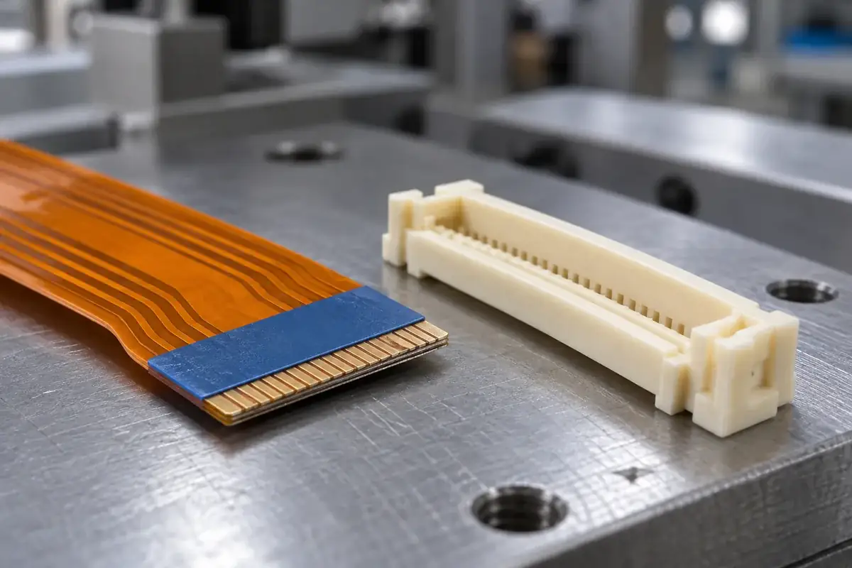
A cable can share the right conductor pitch and still fit poorly in an FPC connector. The connector receives a physical stack of conductors, insulation, adhesive and sometimes a local stiffener. That stack has a position and a shape as well as a nominal thickness. Matching only the pitch leaves the surfaces responsible for insertion and closure largely unexamined.
Thickness questions become harder when a drawing gives one value without naming where it applies. The exposed contact region, reinforced insertion end and flexible length may not have the same construction. Before changing a molded slot, identify the actual cable section that passes through it and the section that remains inside the closed mechanism.
Product design illustrations accompany the molded-component engineering explanations below.
Start with the local cable stack
A stiffener can help the insertion end resist folding, yet its edge may introduce a step close to the housing entrance. If that step meets the entrance too early, the cable can appear seated while the conductive region is still short of its intended position. Moving the stiffener edge or changing the housing lead-in affects different functions and should not be treated as an equivalent correction.
The adhesive layer deserves attention because it is part of the local stack even when it is not visible from above. A cable drawing should clarify the accepted total thickness and the region over which it applies. Adding nominal layer values independently can produce a stack that does not represent the finished supplied cable or its approved measurement condition.
Edges also matter. A square, cleanly cut end enters differently from a curled or uneven edge even if a thickness measurement at the middle is acceptable. A compliant cable can bend around an obstruction and create misleading feedback during assembly. Review the leading edge, reinforcement boundary and flatness together before assuming that the housing needs more clearance.
Molex's 5027904091 listing explicitly identifies its cable type as FPC only. Product-specific compatibility statements matter: a connector family name does not establish that every FFC or FPC construction can be substituted.
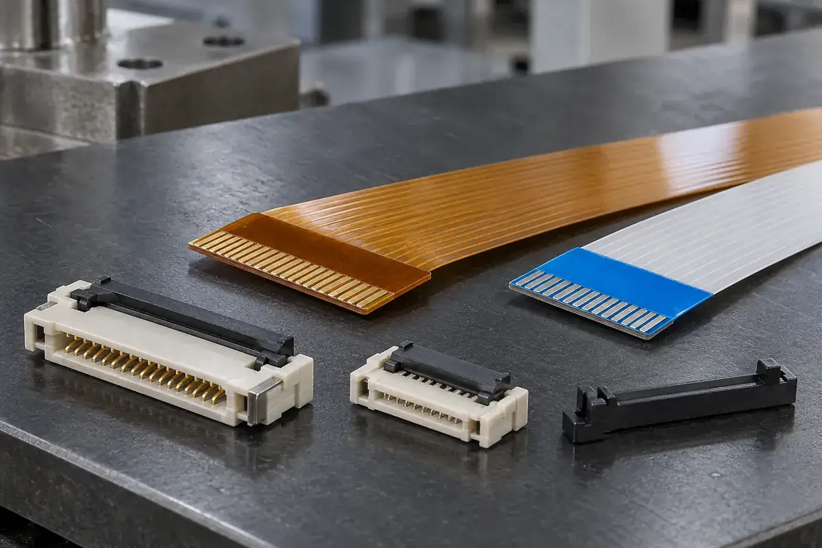
Separate insertion clearance from the closed condition
When an actuator is open, the cable needs a clear insertion path consistent with the connector design. When it is closed, different surfaces may govern support, contact loading and retention. Enlarging the housing opening can relieve an insertion problem while changing cable position in the closed state. The two conditions belong in the same review even though they are inspected separately.
A narrow entrance can be created by local flash, housing bow or the relative position of internal components. Those causes will not all respond to the same tooling correction. First determine whether the obstruction exists in the bare molding, after component assembly or only when mounted. This sequence avoids compensating in the plastic drawing for a condition introduced elsewhere.
Likewise, a loose-feeling cable does not prove that the slot is too large. The selected contact system may establish the working support after closure. The cable may also be insufficiently seated or presented in the wrong orientation. The contact-orientation review helps eliminate one important source of apparently inconsistent fit.
An illustrative fit study can compare the same identified housing with controlled cable samples at the relevant dimensional conditions. Record the support and operation method rather than relying on hand feel alone. Such a study helps assign a cause, but it does not justify a general allowable cable range for other connector designs or grades.
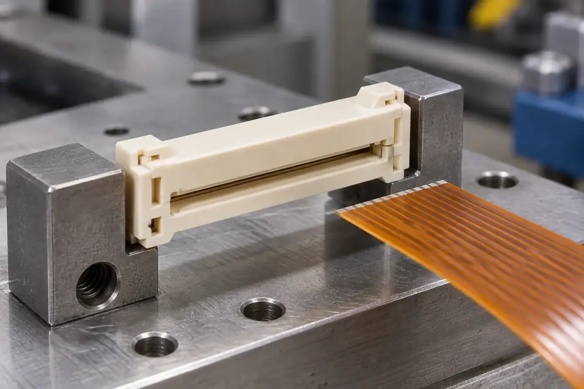
Keep the cable reference connected to the housing datum
Thickness is measured normal to the cable surfaces, while many housing dimensions are defined from a board-side or external reference. The assembly definition must connect those systems. Otherwise, an acceptable slot height and an acceptable cable thickness can coexist with an incorrect cable center position relative to the contacts or the actuator pressure surface.
A long entrance can vary along its width. Measuring only near one end may miss the central restriction or an opening that widens when the housing is clamped. The inspection plan should cover the functionally relevant locations without turning every point into an independent arbitrary tolerance. Flatness, profile or an agreed functional method may describe the relationship more directly.
Contacting gauges need particular care with thin plastic. A gauge that spreads the housing walls can report a pass while changing the geometry it is supposed to inspect. An optical approach avoids some contact forces but still requires controlled focus, lighting and part support. The suitable method depends on feature access and the actual acceptance question.
For the cable, the measuring force and support condition can influence the result where the stack is compliant. Agree those conditions with the cable supplier and use them consistently in development records. Comparing measurements made under unlike conditions can create a false disagreement that neither a new housing tool nor a tighter cable tolerance will resolve.
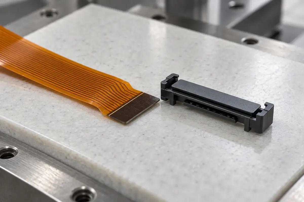
Change the feature responsible for the mismatch
If the stiffener edge stops at the mouth, the leading geometry and insertion depth need attention. If the cable reaches the stop but the actuator binds, review the closed stack and mechanism. If fit changes across the width, inspect bow, skew and distributed support. Naming the failure state narrows the change and reduces the chance of weakening a useful locating feature.
A generous chamfer can ease entry but reduce the length of a guide surface. Increasing clearance may accommodate variation while permitting more angular movement. Thickening a cable end may improve handling while increasing closure load. These are engineering trade-offs, so the preferred change depends on the whole mating sequence rather than a general preference for easy insertion.
The related article on insertion depth explains how thickness and seating interact. A valid trial needs both a compatible local stack and a known final cable position. Neither a successful closure nor a visually straight cable alone establishes that the conductive regions occupy the intended relationship.
For custom molded FPC and FFC housings and actuators, supply the cable construction and relevant counterpart definition with the plastic drawing. An injection molding review can then assess the actual slot, support and release geometry. The result should be a controlled interface definition, not an unsupported universal cable-thickness claim.