
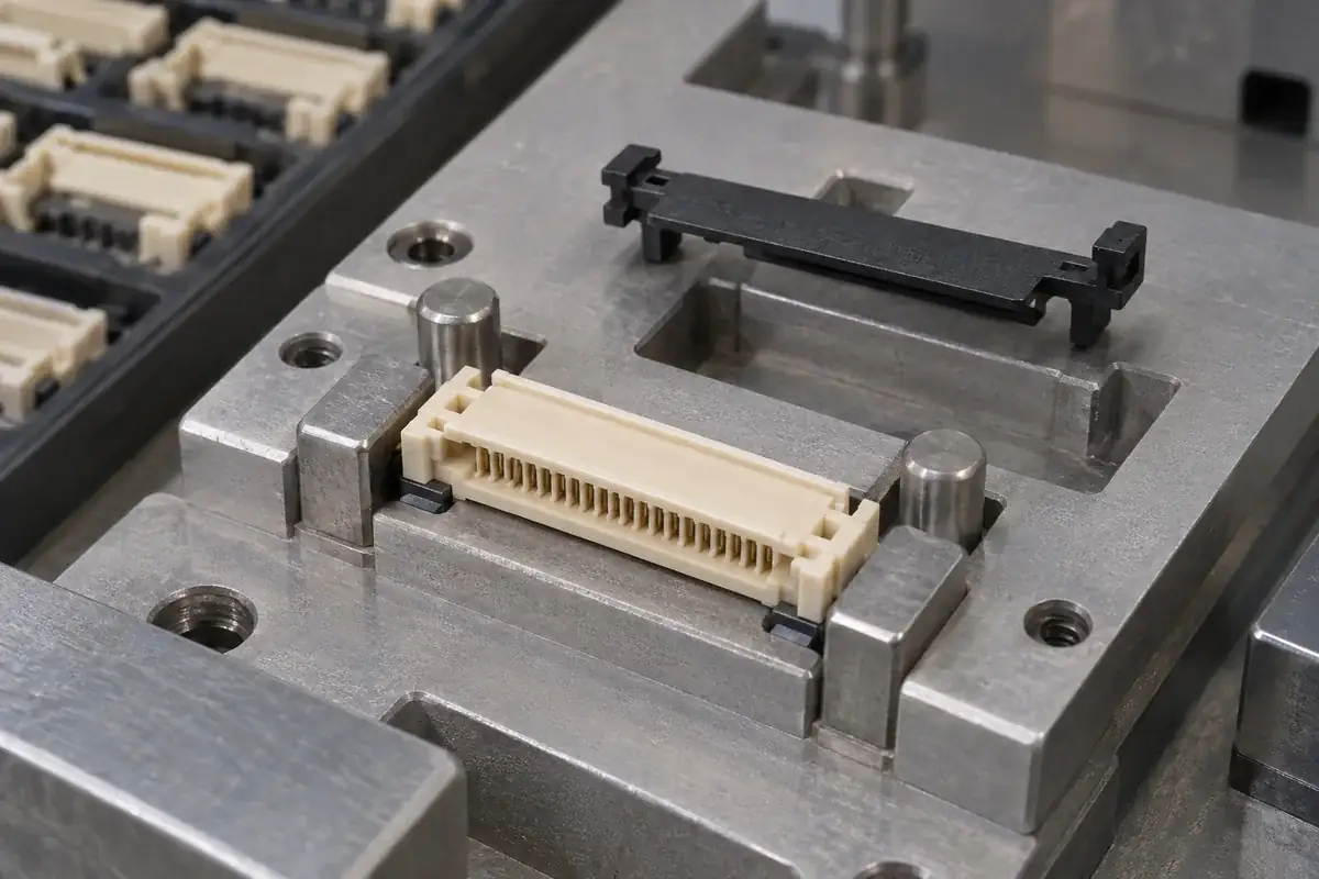
A fixture can make a small connector assembly easier to handle while also making a poor fit look acceptable. If it forces a bowed housing flat, spreads support ears or holds an actuator square beyond the point of assembly, the fixture may temporarily supply a function that the delivered parts cannot provide. Good workholding stabilizes the intended operation without hiding the condition being evaluated.
For FPC housings and actuators, begin with the component assembly sequence. Identify where each loose part is located, which surfaces receive force and when support is removed. Cable mating is a later operation with its own instructions; a fixture for installing an actuator should not be designed by simply imitating the final connector's cable-insertion motion.
Product design illustrations accompany the molded-component engineering explanations below.
Locate from features that matter to the assembly
An outside wall is convenient to touch, but it may not be the best reference for aligning two pivots or a pair of slider rails. The datum scheme should connect the fixture to the functional features without overconstraining a thin housing. If several locators compete to define the same direction, small part variation can create unpredictable contact and orientation.
Separate locating from clamping. Locators establish position; clamps keep the part against the intended references during the operation. A clamp that pushes across a cable slot may change the slot itself. Place holding forces through supported structure and confirm that the force required to retain the component does not distort the interface being assembled.
A nest can provide local support beneath housing ears where actuator installation creates a reaction. That support should be deliberate and accessible for cleaning and inspection. A chip or fragment beneath one ear can tilt the component and convert a balanced operation into a one-sided load. Small parts do not make fixture condition less important.
The pivot and end-stop article explains why a pivot must not become an unintended lever during installation. The fixture should align the relevant features before applying the assembly force. If the intended process requires temporary deformation, its location and direction must be defined rather than left to the operator's judgment.
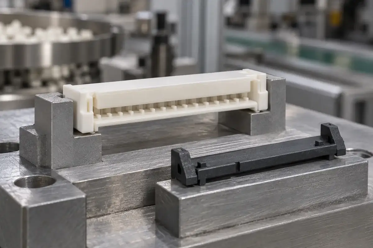
Control the force path through the moving component
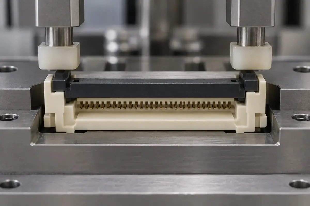
A broad pusher can appear gentle while contacting the actuator only at a raised central feature. The resulting bend may delay engagement at both ends or damage a local wall. Design the contact face from the actual actuator geometry and required operation. Confirm where it touches before using it to explain an assembly-force result.
Symmetric loading can help a long component move evenly, but equal pusher positions do not guarantee equal reactions. Part geometry, fixture alignment and contact timing still matter. A compliant or independently guided contact arrangement may be useful in some designs, provided it does not mask unacceptable end-to-end variation. The choice should follow the mechanism's requirements.
Travel limitation belongs in the fixture as well as in the part review. A pusher should not continue loading a delicate stop after the required assembly state has been reached. However, a machine stop set from an arbitrary external height can also halt the operation too early. Relate fixture travel to a verified component seating condition.
Hirose's FH23 guidance includes connector-specific actuator operation requirements, including end loading for certain versions. It illustrates why force application cannot be generalized from one connector size or mechanism to every other design.
Preserve the evidence when the fixture opens
The component should remain in the intended state after workholding is released. If a pivot disengages or a housing springs into a different shape, the fixture-supported result is not representative. Include release from the nest as an explicit part of the evaluation rather than inspecting only while every support is still engaged.
An observation window can help confirm seating, but it should expose the actual functional reference. Seeing the actuator top become level is weaker evidence than seeing the intended capture feature in its seat. Select the view that distinguishes a complete assembly from the plausible incomplete states identified during design review.
Where an operation uses force or displacement monitoring, the accepted signal needs correlation with identified physical conditions. A repeatable curve can describe a repeatable wrong operation. Use known component revisions and inspect the resulting assembly before assigning limits. Numerical monitoring is useful only when its meaning has been established for that process.
Keep component identities through the trial. Housing cavity, actuator cavity, material lot where relevant and drawing revision can explain patterns that disappear when samples are mixed. The travel and latch-engagement review discusses why a matched pair is not enough evidence for interchangeable supply.
Design handling and maintenance into the operation
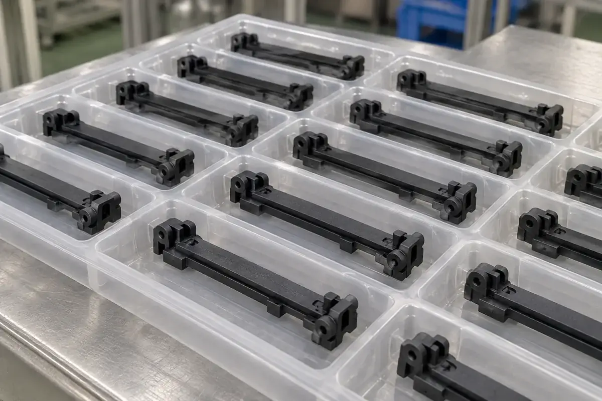
Loose actuators should arrive at the nest without their pivots or latch arms becoming entangled. Individual pockets, controlled orientation and an accessible pickup region can reduce handling damage. Packaging is part of the sequence, especially when the installed component is robust but the loose molding has exposed slender features.
Fixture surfaces wear and collect debris. A locating edge that gradually rounds can shift the assembly reference, while a damaged pusher face can concentrate load. Define the surfaces whose condition matters and make them inspectable. Replaceable wear elements can be useful if their own locating interfaces preserve the required relationship after replacement.
The same nest should not automatically serve as the final dimensional gauge. Assembly workholding may intentionally constrain a part, whereas inspection may need to reveal its free-state geometry. Separate the purposes or document the different support modes. Otherwise, every production check can reproduce the same hidden correction introduced by the fixture.
For custom molded FPC and FFC housings and actuators, share the intended assembly supports with the component drawings. An injection molding and sample review can then distinguish part geometry from fixture influence. The best fixture makes the intended operation repeatable and leaves the resulting component condition visible when its job is finished.