
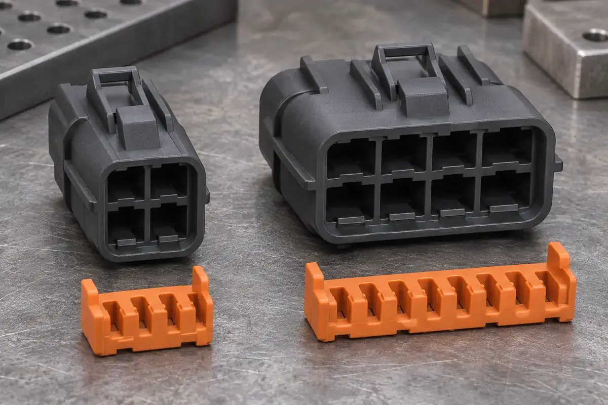
A common lock across several connector sizes can simplify purchasing, feeding and replacement stock. The attraction is easy to understand when the housings belong to one visual family. Yet a shared color, terminal series or nominal pitch does not establish a shared locking interface. The smallest differences often sit inside the housing, where they are least obvious in a catalog view.
Begin by defining what would actually be shared. A TPA that reaches individual terminal-retention features has a different commonality problem from a CPA that acts beside one mating latch. The former may follow a repeated cavity pattern; the latter may be less directly tied to cavity count. In both cases, interchangeability must be demonstrated for the intended components and configurations.
Product design illustrations accompany the assembly and manufacturing explanations below.
Map the interfaces before comparing the outer shape
For a terminal lock, locate the terminal shoulder, groove or retaining feature that the lock must engage. Then relate it to the housing datum used to position the lock. Two housings can share cavity spacing while placing the relevant terminal feature at different depths. A clip that enters both housings may therefore engage correctly in only one of them.
Repeated teeth also need to align with the correct rows and orientations. A wider housing may add cavities, change a central divider or introduce a different terminal type within the same shell. Review the full arrangement rather than extending the shortest version by pattern alone. A repeated feature in CAD is a design convenience, not evidence that the assembly interfaces remain identical.
Consider the manufacturer example of TE's ten-position dual-row TPA, which identifies both its position count and its associated product drawing. That specificity is useful when defining a custom component. A family name is not a dimensional specification; the applicable housing and lock revisions must be part of the proposed commonality review.
A CPA may engage a local housing latch rather than spanning every terminal cavity. This can make a shared component more plausible across a family, provided that the latch geometry, slider path and final stop are genuinely common. The review still has to include each mating pair. A similar top surface does not establish identical behavior during partial and complete mating.
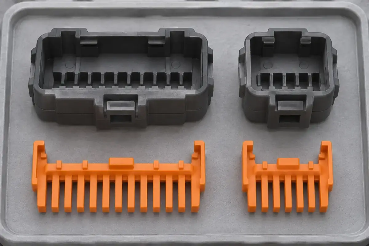
Preserve the guide, stop and retaining relationships
Guide rails determine how the lock approaches its working position. Their spacing, length and entry details should keep the intended orientation while allowing the required travel. If a common clip needs unusually loose rails to fit several shells, it may gain enough tilt to contact the wrong surface. Review the worst permitted combination rather than relying on a carefully aligned nominal assembly.
The pre-lock and final-lock stops need separate attention. A stop that holds the clip safely clear of the terminals in one housing may leave it partly obstructing another. Likewise, a common final position does not guarantee the same overlap with each retaining shoulder. Trace both positions back to the functional interface, and include the tolerances that connect them.
Lock retention within the housing is another interface. A common tooth pattern can coexist with different side hooks, latch windows or wall thicknesses. Those differences may affect insertion, handling and release. Determine whether the shared component is intended to remain captured during service and whether every housing offers the same controlled release route.
A longer span can also change how the part is supported. A narrow lock and a wide lock with similar end details do not necessarily deflect in the same way. If a shared part is supported differently across the family, evaluate how it behaves when pressed off center or when one end reaches a stop first. Avoid assuming that acceptable fit in the shortest housing covers the wider arrangement.
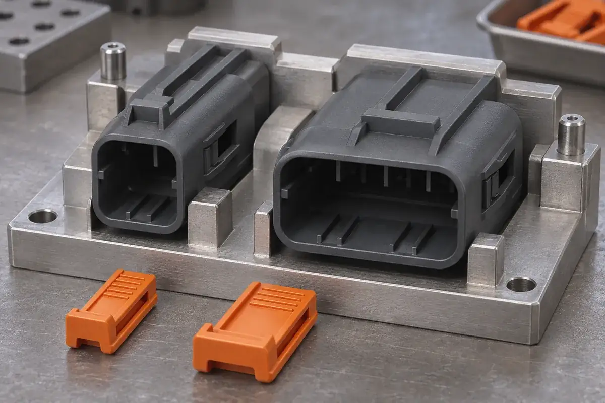
Check the family in its populated assembly states
Commonality can fail after the wires are added. A lock that is accessible on a small housing may be surrounded by a denser wire bundle on a larger one. Include the operating surface, assembly fixture and permitted wire exit direction when comparing variants. The shared geometry needs to support a practical process, not only an unobstructed bench fit.
Partially populated connectors deserve their own configuration review. Empty cavities, cavity plugs and omitted contacts can change what the lock encounters during closure. If the shared concept relies on a particular terminal feature to prevent an incorrect state, establish how it behaves when that terminal is intentionally absent. The unused-cavity TPA review addresses this distinction in more detail.
Review service in the same way. A common clip can be convenient for replacement stock, but only if it can be identified, released and reinstalled correctly in each housing. A service tool may need different access around a larger shell or an installed cover. Document any variant-specific step instead of describing the entire family as having an identical service procedure.
Material and component conditioning belong in the comparison. Housings from different tools or material grades can respond differently to temperature, moisture and assembly strain. Even when nominal dimensions match, the accepted combinations should use the actual production definitions. A shared part should not become an excuse to substitute an unreviewed housing or polymer because it appears to fit.
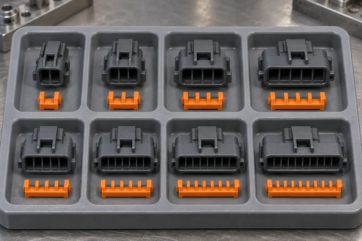
Define an approved combination, not an informal substitution
The output of the review should identify the combinations that are intended to work together. Record housing revisions, terminal configurations, lock revision and any required accessories. The list may conclude that one lock serves several variants, or that only a common design principle is appropriate. Both are useful outcomes when they follow the actual interface evidence.
Evaluation should include the conditions most likely to expose a mismatch: relevant tolerance extremes, specified partial-assembly states and the permitted service operations. Define the acceptance criteria before comparing samples. A component that can be forced into an alternative housing is not a successful shared part, especially if the operation damages a feature that is difficult to inspect afterward.
For tooling development, distinguish geometry that is deliberately common from geometry allowed to vary by cavity count. That distinction helps manage mold inserts, dimensional inspection and later revisions. If a shared surface changes, assess all affected assemblies rather than approving the change against the product that happens to be in production that week.
When requesting custom secondary locks for a connector family, send the complete proposed housing set and identify the commercial reason for commonality. Manufacturing review can then compare the savings with the extra interface and validation work. The goal is a controlled family of components, with shared parts where they make functional and commercial sense.