
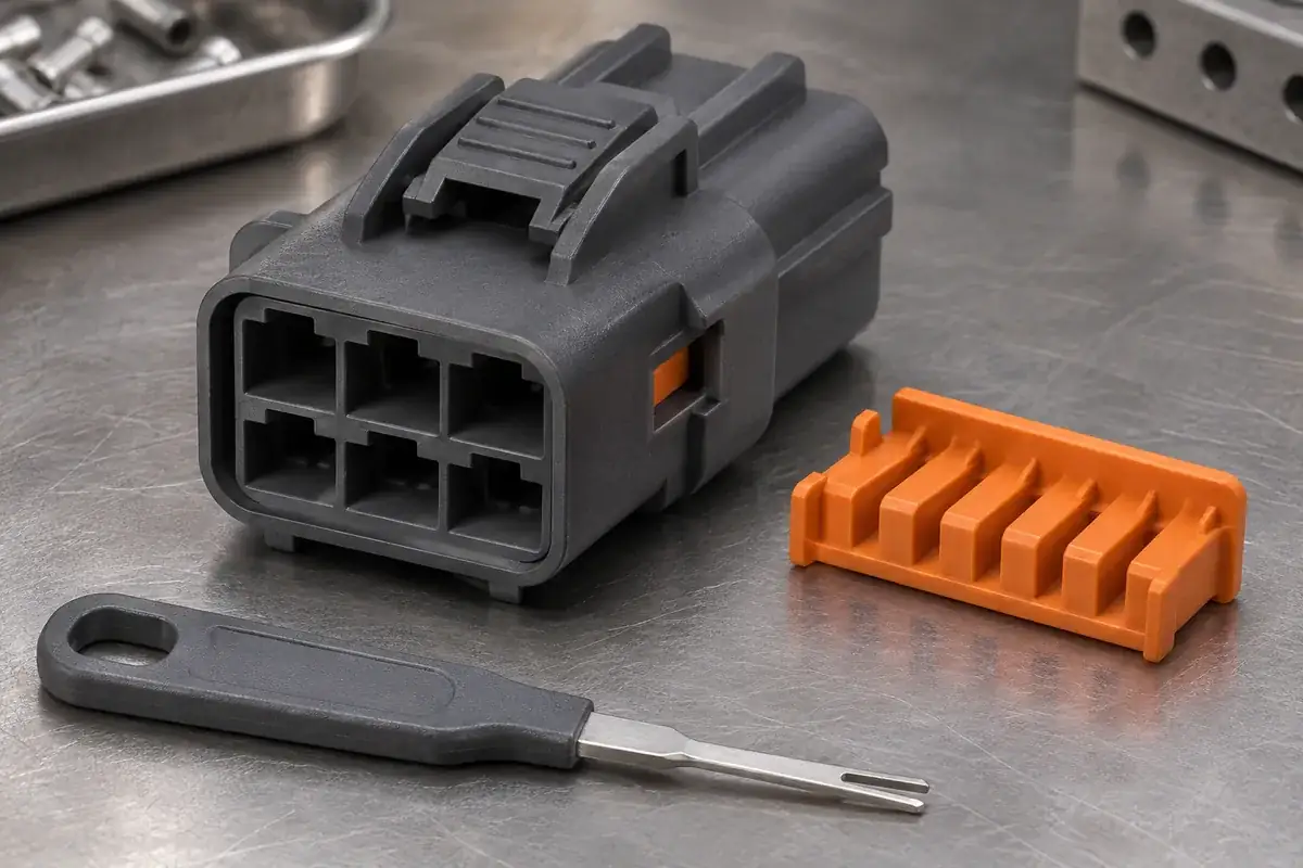
A secondary lock can be easy to install at the harness bench and frustrating to release once the connector is surrounded by wires, brackets and covers. When a repair ends with a broken hook, the immediate explanation is often excessive force. The more useful question is whether the intended release surface was reachable and supported throughout the operation.
Service access should be designed alongside the lock's retaining function. A small window is not enough if the tool cannot approach it at the required angle or if levering against its edge bends the housing. Review the installed assembly, the tool and the sequence together, then decide which molded features need to guide, stop or support the motion.
Product design illustrations accompany the assembly and manufacturing explanations below.
Release the right mechanism in the right order
Start by identifying what the lock actually restrains. A TPA acts at the terminal or contact-retention interface, while a CPA acts at the mated connector interface. The service sequence depends on the exact system. Opening a visible secondary latch does not necessarily release the terminal, and operating a terminal lance does not necessarily permit a still-locked connector pair to separate.
The Molex extraction-tool specification illustrates this distinction through series-specific procedures: access preparation and movement of the TPA precede terminal removal for the relevant housings. Its tool and travel details belong to those listed components. For a custom design, establish the equivalent sequence from its own geometry rather than adopting a familiar tool by appearance.
Map the transition from the delivered condition to the service condition. A lock may return to a retained intermediate position, require complete removal, or be unsuitable for reuse after a particular operation. Those are different design decisions. Define which components remain captured and which are replaced so the technician is not forced to discover the limit by pulling harder.
Consider what happens when the sequence is attempted out of order. A terminal extraction tool may contact the secondary lock instead of the primary retaining feature, or a closed CPA may prevent the mating latch from moving. The aim is to expose the correct next action clearly. It is usually more useful to prevent misleading access than to add a larger opening everywhere.
Design the tool envelope, not just its tip
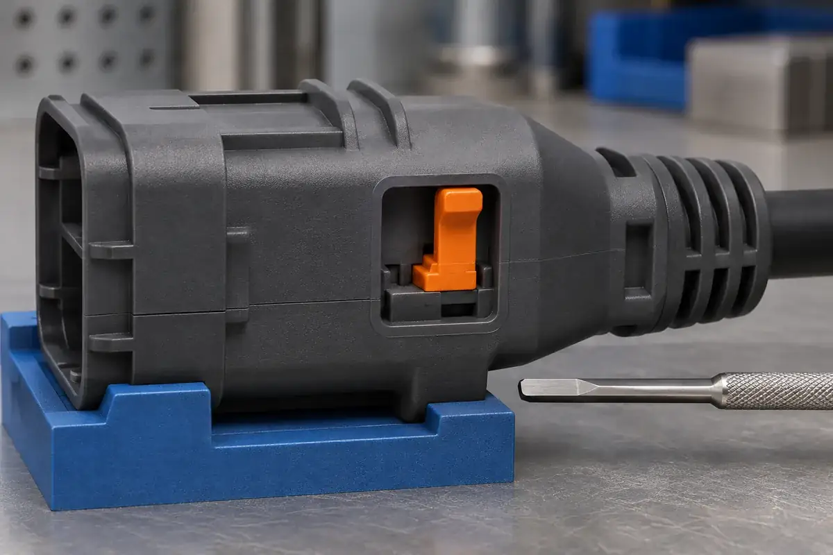
A CAD section through a narrow release hole can suggest ample room while hiding a collision just outside that section. Include the tool shaft, handle and any change of angle needed to engage the feature. A straight insertion followed by rotation needs a larger swept envelope than a straight insertion alone, particularly beside a bracket or a neighboring connector.
Decide where the tool is allowed to react against the assembly. If the operation requires leverage, identify the intended bearing surface and how it is supported. A thin cosmetic rim is a poor accidental fulcrum because its deflection changes both the load and the direction applied to the lock. An appropriate support can make the release action more repeatable.
Provide a clear distinction between the feature to release and nearby openings used for molding, inspection or drainage. Similar-looking recesses can invite the wrong tool path. Shape, location and the assembly instructions can work together to guide access. The design review should also consider whether flash or a gate vestige could obscure the intended tool contact on the finished part.
A tool stop deserves its own review. Limiting insertion can keep the tip from reaching a terminal, seal or opposite wall, but the stop must not prevent the required release movement at the tolerance extremes. Review both functions with the actual tool drawing. Tool access is an interface requirement, just like the terminal extraction path through a wire-to-board housing.
Recheck access after the wires and covers are installed
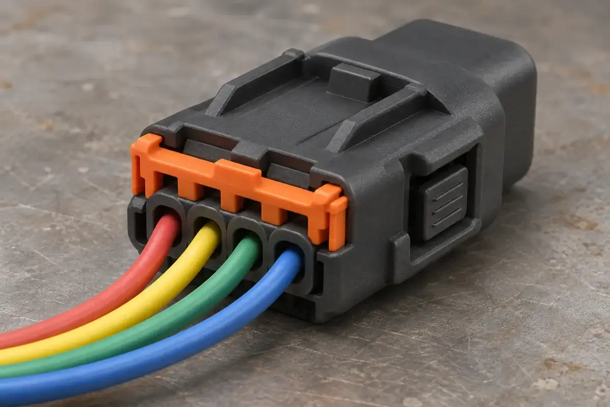
An empty connector gives a misleadingly generous view of the lock. Populate the intended cavities and include the permitted wire sizes, bend direction and dress cover. A wire bundle can block the tool's starting position even when it does not cross the release window itself. The repair sequence may therefore need a deliberate cover-removal or bundle-release step.
Check the likely repair position inside the equipment. A harness may have enough slack for terminal insertion during manufacture but too little to turn the connector around during service. Moving a bracket, unplugging the pair or supporting the shell outside its installed position can be valid procedures if they are defined and practical. Treat the available movement as part of the design input.
For locks retained at both ends, consider how the first end behaves while the other end is released. A wide lock may twist, re-engage or overstress one hook if the procedure assumes a simultaneous movement that the available access cannot provide. The housing guides and service detents should be reviewed against the chosen sequence rather than judged from a single fully open view.
It also matters how the connector is held. Pulling on the wires while trying to release a lock can preload the retaining interface and make the operation feel unusually stiff. A suitable nest or holding surface can isolate the service motion from that load. Define the support condition when evaluating samples so different operators are not effectively testing different mechanisms.
Make reassembly part of the service review
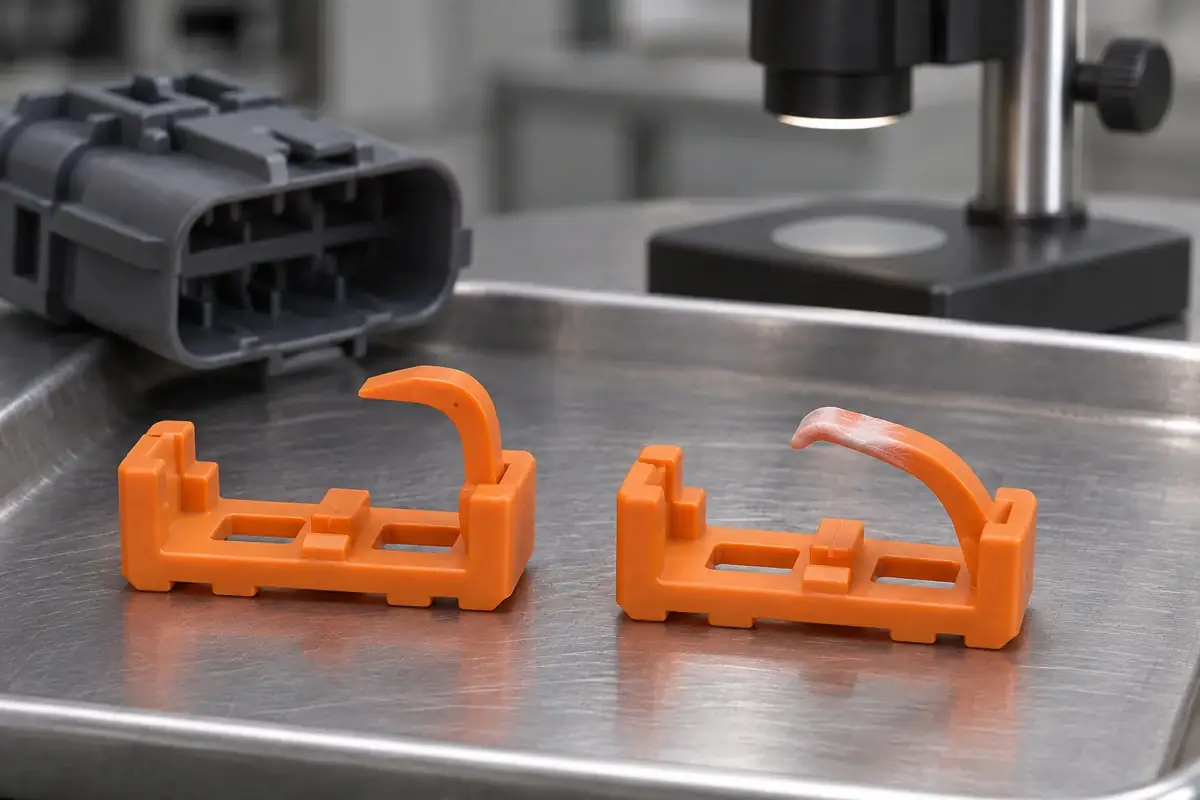
A successful removal is only half the task. Inspect the surfaces that must retain the lock after reassembly, including its hooks, guide rails and the housing shoulders they engage. Whitening, permanent bending or a chipped edge may change the next locking action. A part that can be pushed back into place has not, by that fact alone, demonstrated restored retention.
Establish the intended number and conditions of service operations with the application owner. Evaluation should use identified resin, component revisions and environmental conditioning appropriate to the equipment. Avoid turning a few convenient bench openings into a general reuse claim. The question is whether the specified assembly can still meet its agreed functional acceptance after the intended service sequence.
Bring the release window and supporting walls into the mold tooling review. These features can be sensitive to parting-line placement, local flash and changes made to simplify steel. The moldable design should preserve the tool's intended contact and stop surfaces, while the inspection plan should identify defects that would make those surfaces difficult to use.
For custom connector secondary locks, send the lock, housing and tool models together with the installed arrangement. Describe the release order, captured positions and replacement policy. That information allows the molded-part review to address the complete repair operation and helps prevent a small access problem from becoming a recurring damaged-lock problem.