
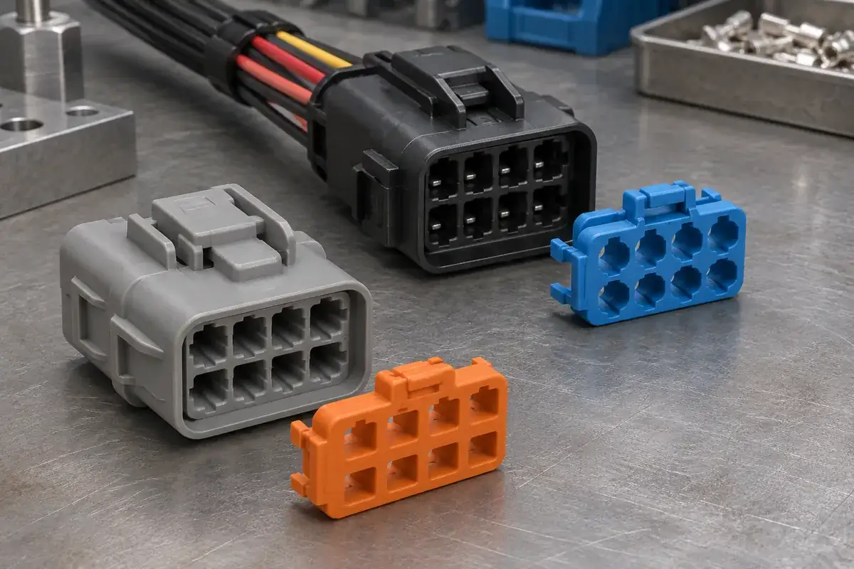
A terminal lock can be easy to reach on a loose connector and difficult to operate once the harness is installed. Choosing an access direction therefore starts with the assembly surroundings. The mating face may be clear during harness production but hidden against equipment later; the rear may remain exposed while a dense wire bundle blocks the actuator.
For this comparison, front means the connector mating-face side and rear means the wire-entry side. These descriptions concern how the lock is installed or reached, not a standardized mechanism. Side-loaded, hinged and other constructions are also possible. Establish the actual movement of the proposed lock before comparing its apparent position on a product photograph.
Product design illustrations accompany the assembly and manufacturing explanations below.
Begin with the contact interface, then choose an approach
The lock still needs to engage the terminal or retention feature at the correct location. Moving the actuator from one side to another does not remove that requirement. Trace the component from the accessible push surface to its functional engagement features, including any long arms or bridges needed to carry the motion through the housing.
Molex's contact-retention guide shows different ways terminals and TPA parts cooperate. Use the selected terminal drawing and housing architecture to identify the required engagement, rather than assuming every front plate or rear insert performs the same job. Access direction is one design choice within that larger retention system.
A front-access arrangement can leave the wire-entry region relatively clear. It may also present the lock near a useful inspection view of the contact cavities. However, the lock cannot obstruct the mating envelope or expose a feature that is easily damaged during connector handling. Its final position must agree with the terminal protection and mating-face requirements.
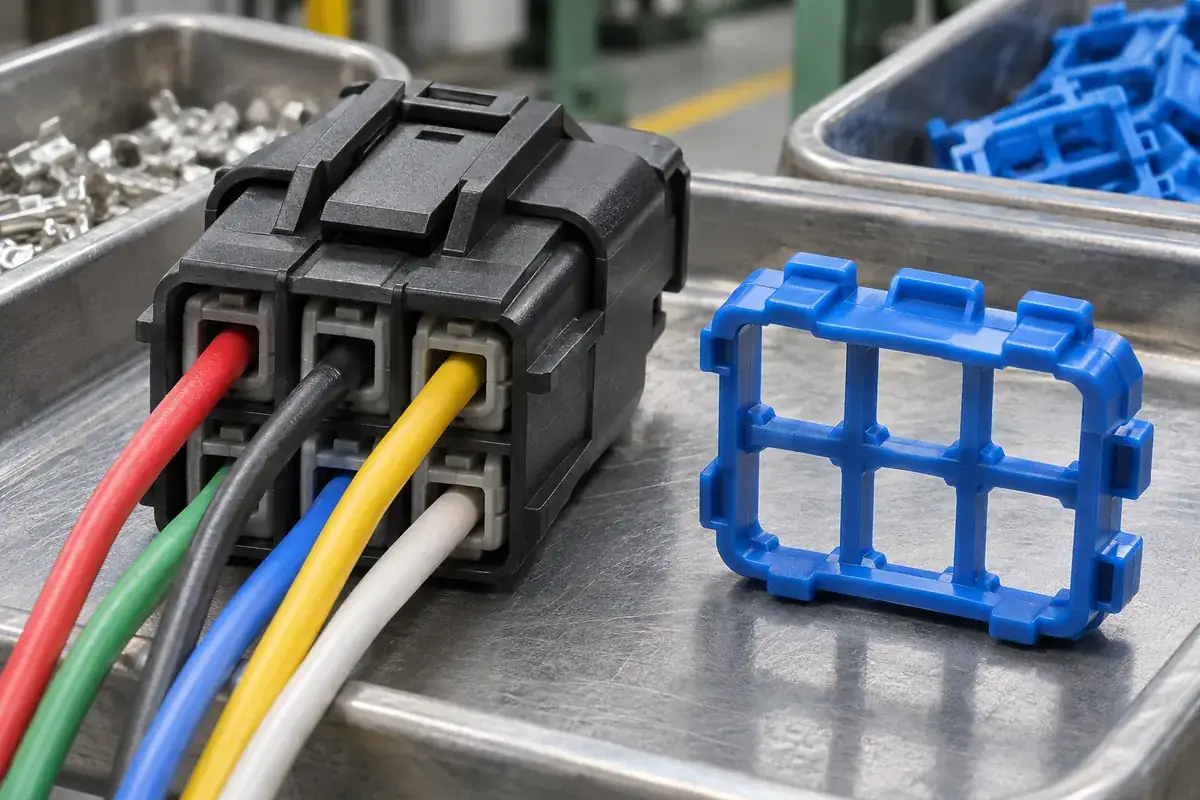
A rear-access arrangement can place the actuator near the harness assembly operation, but the installed conductors and accessories become part of its working space. Review whether the lock passes over the wires, slides beside them or closes around a prepared bundle. These paths have different implications for assembly order, contact loading and later wire replacement.
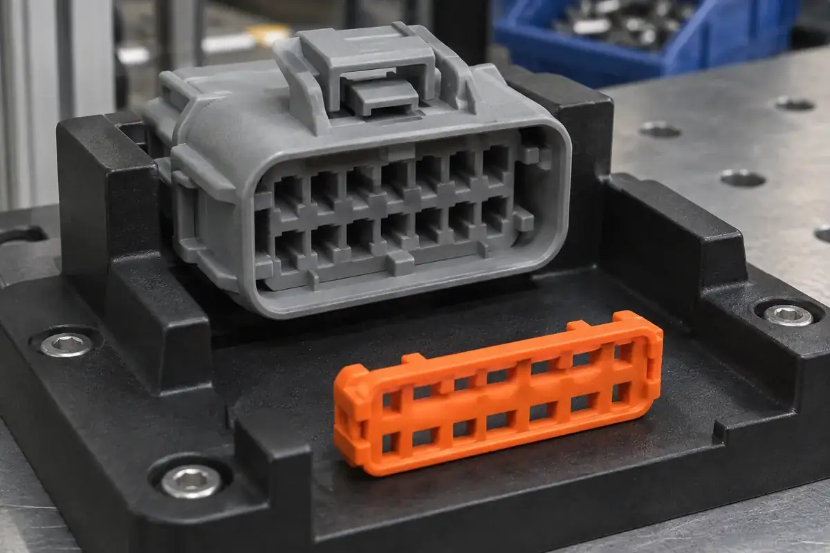
Review the fully populated condition
For rear access, draw the actual wire envelopes rather than centerlines alone. Insulation diameter, wire bend and the grouping of neighboring circuits can change what remains reachable. A gap that looks generous in an empty CAD model may disappear once the harness is dressed. Avoid solving the problem by forcing wires into a sharp bend against the lock actuator.
Include seals and rear accessories in the same review. A wire seal can restrict where a terminal or lock may move; a rear cover can hide the release path. If the lock must be operated before a cover is fitted, the production sequence should make that order clear. If service requires removing the cover, make sure the cover can actually be released in the installed position.
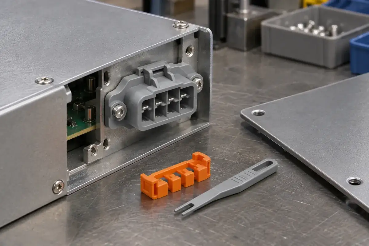
Front access has a different crowded condition: the connector may already be mounted through a panel or close to another device. Check whether it must be unmated or removed from its mounting before the TPA is accessible. That may be acceptable for the product, but it should be a deliberate service decision rather than a discovery after the enclosure is finalized.
Compare the most difficult permitted configuration, not merely the nominal one. A longer housing, larger wire option or nearby bracket can change the available approach. If several variants use the same lock, document which surrounding features remain common. Our article on sharing locks across cavity counts looks at the interfaces that need coordinated control.
Give the assembly tool a complete working envelope
The clearance needed by a tool is larger than the opening reached by its tip. Include the shaft, guiding feature and any surrounding fixture during the approach and withdrawal. Check the angle at which the actuator is contacted. An off-axis push can twist a lock or load a thin housing wall even when the tool technically fits through the opening.
The housing support should oppose the intended assembly reaction. A fixture that grips only a flexible mating latch or a narrow rear wall may distort the component while the lock is operated. Identify stable support surfaces and preserve the inspection view. Fixture convenience should not require the lock to operate in a distorted condition that differs from the finished assembly.
For a long front plate or rear bar, consider how force reaches both ends. A single push point can be suitable when the component and guide are designed for it; another arrangement may need broader support. Evaluate skew and partial engagement using the actual permitted variation. The goal is a defined operation, not a universal rule that every lock needs the same actuator shape.
Manufacturing access also extends to the mold. Slender fingers, internal hooks and narrow release slots must be reviewed for tool formation and part release. The accessible assembly direction may not match the most convenient molding direction. Resolve that conflict during mold tooling review, while guide geometry and parting-line locations can still be coordinated.
Choose the arrangement around the product lifecycle
Front and rear access each make some operations easier and others more constrained. Compare contact loading, lock closure, connector mating, installation and the expected repair operation. A high-volume assembly advantage may justify removing a connector for rare service, while a frequently repaired harness may need a more accessible release route. State those priorities before selecting the layout.
Use physical samples or suitable assembly models to review reach and sequence, then evaluate the functional plastic components with their actual counterparts. A clearance model can reveal a blocked tool path without establishing retention force or durability. Keep those conclusions separate so a successful packaging review is not mistaken for validation of the complete connector mechanism.
When requesting custom TPA component manufacturing, supply the access direction, lock travel, housing and terminal revisions, installed surroundings and service expectations. Include the relevant assembly-stage drawings rather than only the final assembly. That information helps turn a convenient-looking lock location into a practical molded component that can be installed, checked and serviced as intended.