
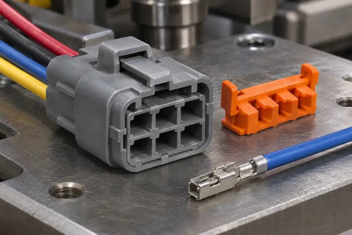
The secondary lock appears closed, yet one contact sits farther back than the others or moves when the harness is handled. It is tempting to conclude that the lock needs a thicker tooth. Before changing the mold, establish whether the terminal, housing and lock belong together, and what the closed position is actually intended to demonstrate.
Some TPA systems combine terminal retention with a mechanical check on terminal position. Others use a different retention arrangement or require additional assembly checks. A closed outer surface is therefore an observation, not a complete diagnosis. The investigation needs to connect that visible state to the internal contact interface without forcing or damaging the suspect sample.
Product design illustrations accompany the assembly and manufacturing explanations below.
Preserve the condition that produced the symptom
Record which cavity is affected, the terminal and wire identifiers, the housing and lock revisions, and the supplied lock position. Keep an untouched sample if possible. Repeatedly opening and closing the same part can change a bent lance, shave a plastic edge or move the terminal into a different position, making the original cause harder to reconstruct.
Check the approved application instructions before performing a pull-back or extraction step. Molex's contact-retention discussion shows that systems do not all retain a terminal in the same way before the TPA is installed. The expected behavior at the preliminary stage must come from the exact connector construction, rather than an assembly habit learned on another family.
Next compare the affected cavity with an acceptable one using a defined reference. The position of a wire jacket can be misleading because strip length, crimp geometry and insulation compression vary. Where the drawing allows it, inspect the contact body or its seating shoulder relative to the housing reference that actually determines terminal position.
A partially visible metal surface is not automatically a fully seated terminal. The feature may be a crimp wing, a lance or a transition rather than the specified stop. Identify the relevant surface on the terminal drawing, then establish a practical viewing or measurement method. This avoids accepting a convenient visual cue that has little relationship to the required position.
Verify the components before changing the plastic
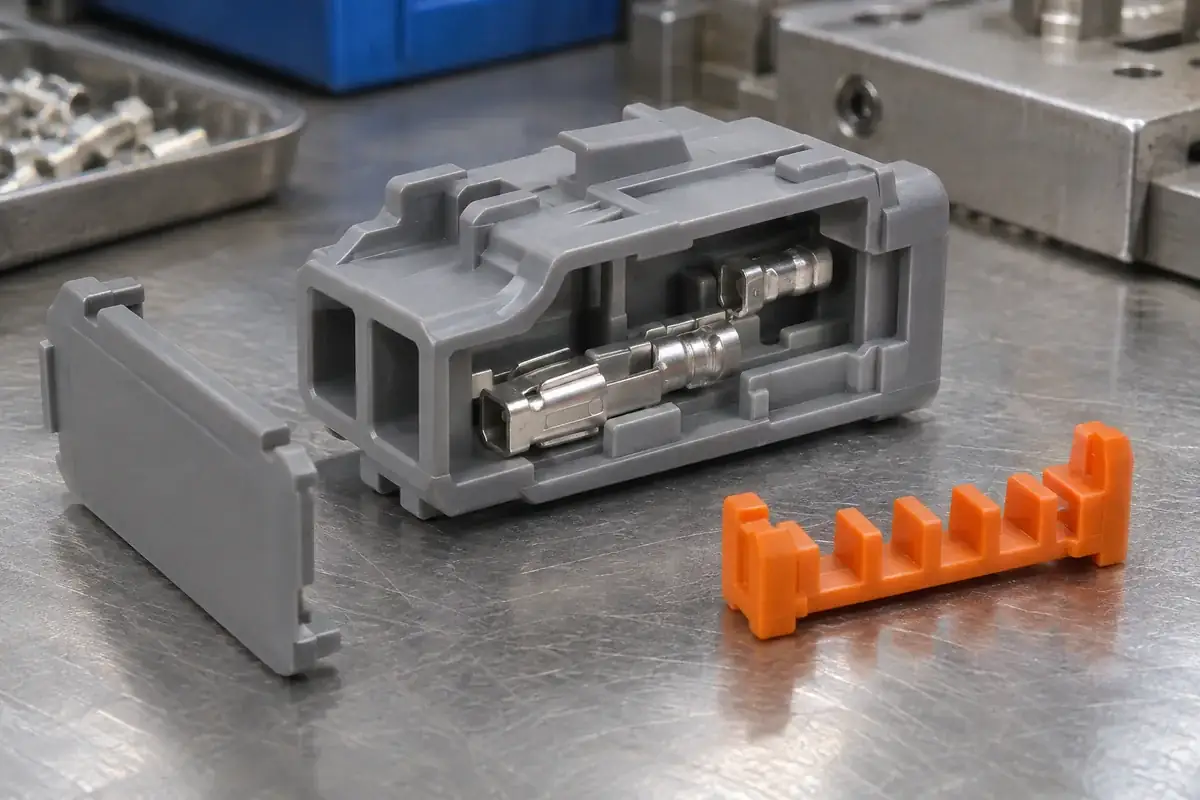
Contacts with similar front profiles can have different retention windows, shoulders or crimp sections. A terminal may enter a cavity and even make electrical contact while lacking the intended engagement with the lock. Compare controlled part numbers and drawing revisions rather than judging compatibility by wire size, color or the apparent width of the contact.
The lock itself also needs positive identification. A similar insert from a different cavity count or housing revision can reach an exterior stop without placing every retention feature correctly. Review the locating keys, guide engagement and functional tooth positions. If the design allows an incorrect insert to enter, the solution may involve error-proofing as well as dimensional correction.
Look at terminal orientation through the entire insertion path. A contact that is rotated or tilted may stop against an internal wall before its intended shoulder reaches the seat. The wire can still appear to have entered far enough. Our discussion of terminal orientation and keying explains why the entry guide and the final retention interface need to agree.
Crimp preparation can create another obstruction. An oversized insulation crimp, a displaced seal or a bent contact body may hold the terminal rearward even when the nominal terminal type is correct. Resolve that interference with the terminal and harness requirements first. Enlarging a housing entrance to accommodate an incorrect crimp can remove guidance needed by correctly prepared contacts.
Trace how the lock reached the apparent closed state
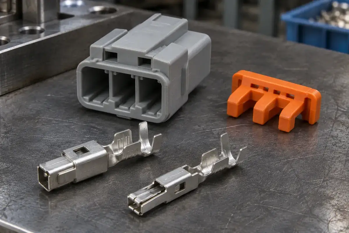
Examine whether both ends of the lock reached the final stop. A long insert can be skewed, with one side latched and the other held proud. Viewing only the accessible end may hide the difference. Define inspection references that reveal the relevant motion, particularly when a wire bundle or fixture obscures one side of the assembly.
Then follow the internal path of the locking feature. A flexible beam may have bent around an obstruction, a tooth may have been damaged, or an unintended clearance may let the insert bypass the terminal shoulder. These are possibilities to investigate, not conclusions from the outside appearance. Sectioning or other internal examination should be planned so the evidence remains interpretable.
Assembly support can affect what happens during closure. If the housing is held by a thin wall or the actuator is pushed off-axis, the assembly may deflect differently from the intended condition. Reproduce the original support and actuation direction with identified samples. Record the actual sequence instead of comparing a fixture-built failure with a casually assembled replacement.
Where position detection is required, review deliberately incorrect states as part of the agreed validation plan. Include the relevant terminal short-seating conditions and observe whether closure is blocked without damage. The displacement range, actuation limit and acceptance rule must be defined for the system; there is no universal push force that proves every TPA works correctly.
Correct the cause and keep the inspection meaningful
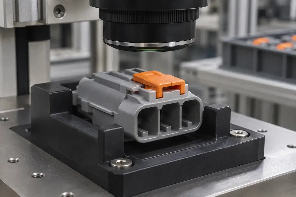
If the issue is incompatible components or preparation, control the identification and assembly process before altering the tool. If correctly specified components still permit the wrong state, examine the tolerance relationships and blocking geometry with the connector designer. A local plastic change can improve one interaction while obstructing terminal insertion, release access or another approved configuration.
The proposed correction should be checked with acceptable as well as unacceptable assemblies. The correct contact needs a practical insertion and locking path, while the defined incorrect state needs the intended response. Review both ends of the permitted component variation where appropriate. A fix that succeeds only with one selected sample does not explain the remaining design margin.
Send the suspect component revisions, observations and assembly conditions with a request for custom secondary-lock manufacturing review. Connect the dimensional findings to the injection molding process only when evidence points there. This keeps the response focused on the interface that failed, rather than making the plastic larger or stiffer simply because it is the easiest part to change.