Process
Liquid Silicone Rubber Injection Molding
This consumer-electronics project review examines a two-cavity liquid silicone rubber tooling concept, with S136 cavity steel, cold-runner gating and slider-assisted part removal. The focus is the DFM decisions and sample checks needed before approving a silicone overmold for production.
Liquid Silicone Rubber Injection Molding
Liquid Silicone Rubber with a Plastic Substrate
Consumer Electronics (3C)

Project Background
Our client submitted 3D geometry for two related silicone parts — a connector seal and a cable grommet variant— targeting a 120-ton LSR press. Both parts require overmolding onto a plastic substrate, which means the mold must accommodate two different material shrinkage behaviors simultaneously within the same cavity.
The engineering discussion covers draft, gating, parting lines, ejection and shrinkage. Proposed geometry changes and the final gate design require drawing approval; the review points below are not a published first-article or production acceptance report.
For more on the underlying process, see our LSR Injection Mold Tooling Capabilities→
Values describe the tooling concept and design targets in this project review, not measured production results or a standard specification for every LSR order. Final values require the approved tooling drawing and sampling records.
| Mold Type | Liquid Silicone (LSR) |
| Cavity Count | 2 Cavities |
| Cavity / Core Steel | S136 Stainless |
| Mold Base Material | A50 |
| Gate System | Cold Runner, 3×0.08 mm |
| Gate Mark (valve) | Ø1.0 × 0.3 mm deep |
| Slider Count | 2 Sliders (S136) |
| Ejection Method | Bar-lift + Slider, Manual |
| Runner Weight | ~5 g |
| Target Mold Life | 300,000 cycles |
| Machine Size | 120 T |
| PL Flash Tolerance | ≤ 0.05 mm |
| PL Step Tolerance | ≤ 0.03 mm |
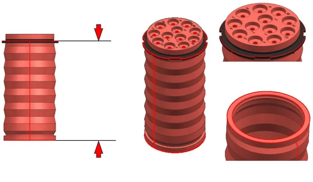
Client 3D files received. No 2D drawing supplied at this stage; DFM proceeds from model geometry only.
Review draft, gate location, parting lines, ejection and shrinkage. Record proposed changes against the drawing revision and obtain customer approval.
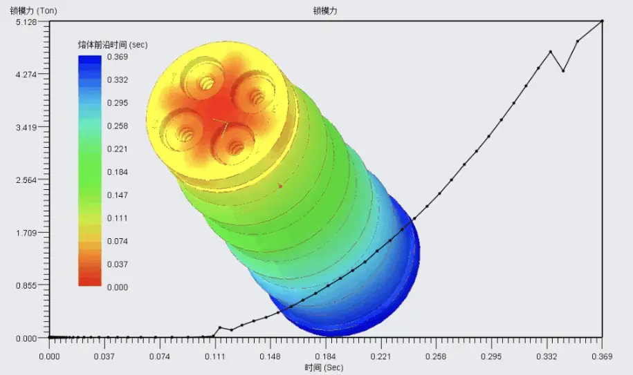
Compare candidate gate layouts using data for the selected LSR grade. Review fill balance, venting, pressure, cure behavior and required clamp force.
Confirm the cold-runner layout, gate geometry, S136 inserts and two-cavity concept against approved drawings before releasing the tool design.
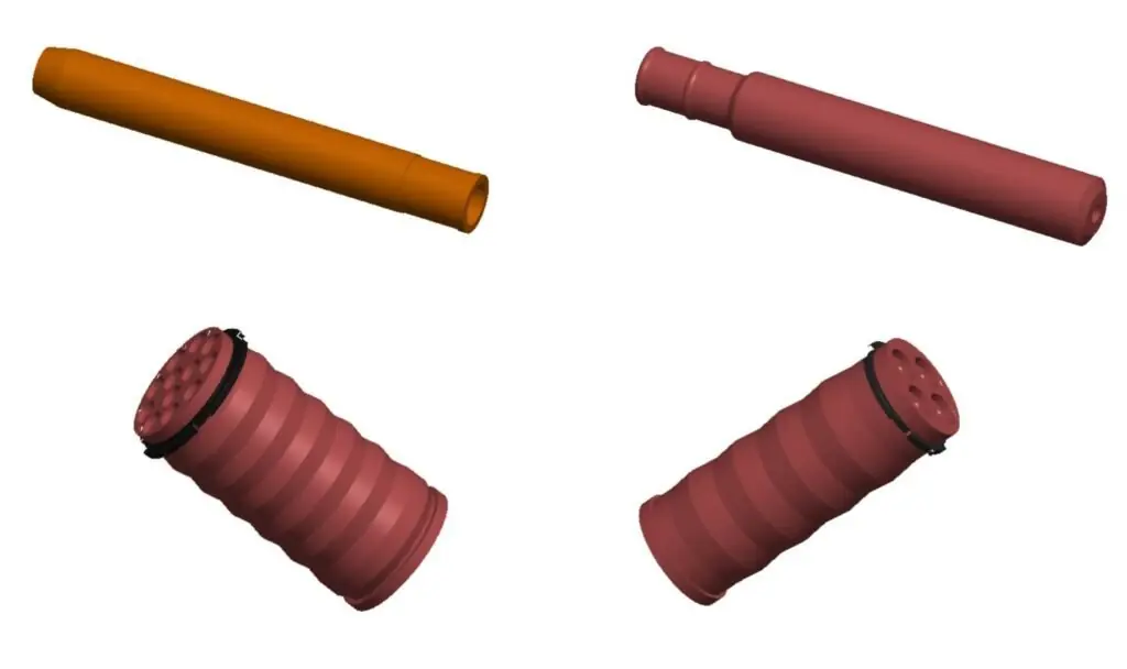
Match steel, shut-off surfaces, cooling and heating circuits to the approved design. Mold-life figures are design targets, not demonstrated cycle-test results.
Agree the first-article dimensional report and functional tests before sampling. Any PPAP or additional approval package is included only when required by the project.
Application, material and contact requirements guide the project review. FECISION coordinates applicable production-site qualifications and documentation with the manufacturing partner. See our manufacturing standards and scope for the distinction between site qualifications and finished-part acceptance.
Question: Do the raw materials and process aids meet the customer's environmental requirements (RoHS, REACH, halogen-free, etc.)?
Answer: The exact LSR grade, colorants and process aids must be reviewed against the customer requirements. Applicable supplier declarations and material lot records are part of the agreed documentation package; a generic silicone description does not establish finished-part compliance.
Question: What is the end-use application of these parts?
Answer: This review concerns internal sealing components for consumer electronics, not a medical-device or automotive qualification program. FECISION coordinates the project with a manufacturing partner. Applicable production-site quality-system scope and customer-specific controls are reviewed for the selected site; its certification is not a certification of FECISION or of the finished component.
Question: Do the finished parts contact human skin or mucous membranes during use?
Answer: The project description identifies enclosed, internal components. The customer must confirm the final contact conditions and intended use. Material suitability and any additional testing are then defined for that use; this electronics example does not demonstrate biocompatibility or patient-contact suitability.
These four review areas explain the proposed changes and the decisions needed before machining. A DFM proposal does not establish that the finished parts have passed inspection; customer approval and sample verification remain separate steps.
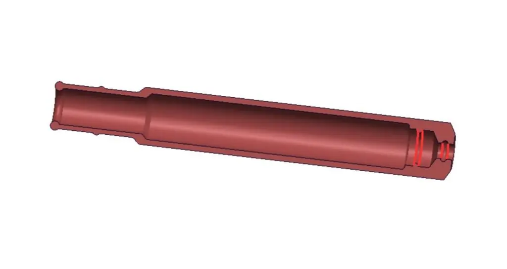
Sharp interior edges can increase the risk of silicone damage during ejection and local stress in tooling features. Corner geometry therefore needs review before machining.
Resolution: Fecision recommended adding R0.3 mm corner radii at all sharp edges on both parts. The client was asked to confirm these additions on both geometry variants before steel was cut.
Recommended radius: R0.3 mm (all sharp corners)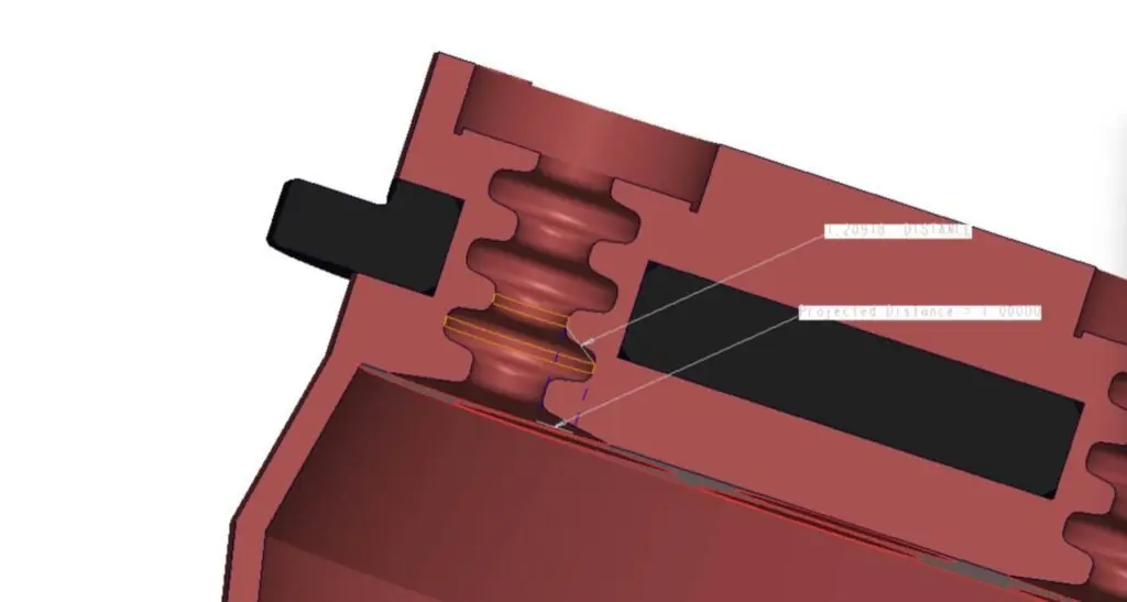
The connector seal contains 12 circular hole positions with 1.0 mm single-side snap depth. For a silicone part at this scale, that undercut force makes clean manual demolding unreliable and risks tearing the cured rubber on each cycle.
Resolution: The DFM proposal reduces the undercut depth from 1.0 mm to 0.5 mm per side. Retention and demolding behavior still need to be checked with the selected silicone grade and approved on representative samples.
Original: 1.0 mm → Recommended: 0.5 mm per side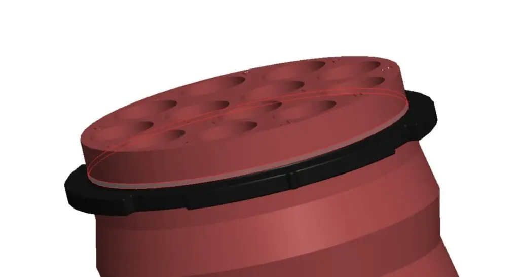
Where the LSR overmolds onto the plastic insert, the plastic side surface is vertical — giving the silicone melt a pathway to creep under clamping pressure and create flash that is nearly impossible to deflash cleanly post-cure.
Resolution: Option A: Apply 10° draft to the plastic side face, creating a self-sealing angle under mold pressure. Option B: Design a deliberate 0.1 mm single-side overflow channel that controls where flash goes rather than trying to prevent it entirely.
Option A: 10° taper | Option B: +0.1 mm overflow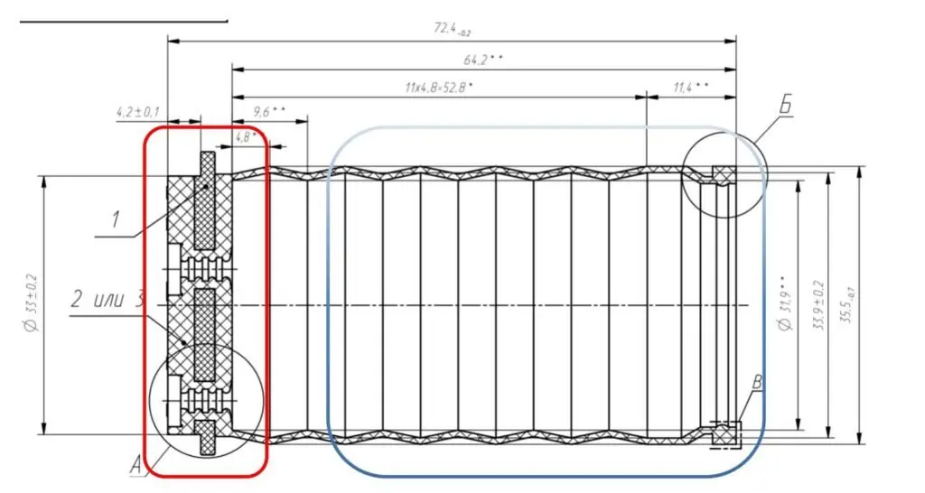
The pre-molded substrate constrains the silicone differently from free-standing silicone regions. Substrate thermal movement, LSR cure shrinkage and post-curing can all affect the finished assembly, so a single generic offset may not suit every feature.
Resolution: Separate substrate-referenced features from free silicone dimensions in the tooling review. Confirm offsets using the exact material data, assembly geometry and sample measurements rather than assuming that a bonded zone has zero movement.
Review substrate-referenced and free silicone zones separatelyGate System Design
The tooling concept uses a temperature-controlled cold runner to feed the heated LSR cavity. Runner temperature, gate geometry and the cure cycle must be matched to the selected compound and tool, keeping the material processable until it enters the cavity.
▲ The review lists a 3×0.08 mm gate detail. The final tooling drawing must clarify the runner-to-cavity connection and any valve-pin geometry; these dimensions should not be copied into another mold without a material and filling review.
▲ A listed gate-mark allowance is a proposed cosmetic or assembly limit, not proof of customer acceptance. Confirm the location, maximum vestige and trimming requirements on the part drawing, then inspect samples.
INRunner: review temperature control and flow to both cavities.
OUTGate: confirm geometry against filling, cure and shear behavior.
MARKVestige: agree allowable marking and check it on samples.
SEALProcess: establish mold and runner settings for the selected grade.
Engineering Verification
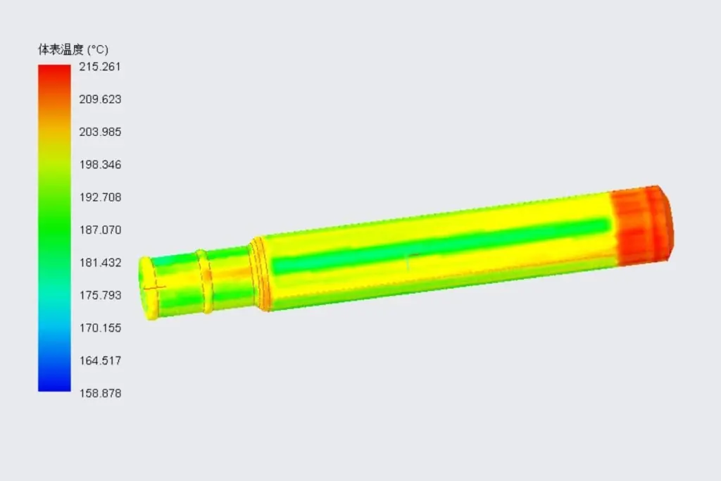
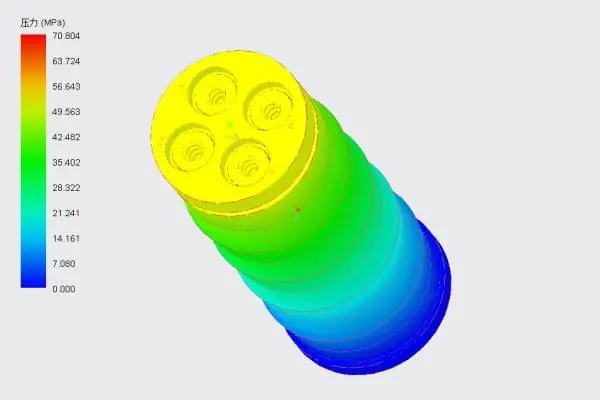
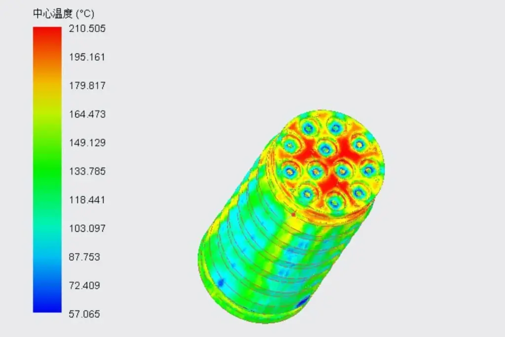
The analysis views illustrate the kinds of questions considered during tooling development. They are not presented here as signed simulation or test reports. Predictions depend on the material model and setup; final approval requires the agreed dimensional and functional sample records.
| Review Parameter | Question to Resolve | Verification Record |
|---|---|---|
| Fill pressure | Pressure and fill history | Material model and trial process record |
| Clamping force | Projected area, cavity pressure and press margin | Tool review and process setup |
| Cavity balance | Relative fill progression in both cavities | Simulation and short-shot/sample review |
| Temperature and cure | Mold temperature distribution and cure progression | Selected-grade data and validated cycle |
| Air traps | End-of-fill zones and venting paths | Venting review and sample inspection |
| Weld lines | Location relative to seal and stressed features | Part-specific functional testing |
| Shrinkage | Substrate constraints and free silicone dimensions | Conditioned sample measurements |
| Gate shear | Shear conditions against grade-specific guidance | Material supplier data and process review |
Compare flow progression through each cavity and around the undercuts. Confirm the gate layout with the selected compound and samples; balanced simulation alone does not eliminate short-shot risk.
Review point: cavity balanceIdentify likely end-of-fill traps near slider interfaces and propose venting appropriate to the tool and compound. Sample inspection checks whether the proposed vents work without unacceptable flash.
Review point: venting and flashMap flow-front meeting points against sealing and loaded features. A simulation color plot is not a mechanical strength test; acceptance depends on the intended use and agreed functional test.
Review point: functional acceptanceReview pressure history, runner balance and clamp-force margin together. Flash also depends on shut-off geometry, fit and material behavior, so pressure alone cannot establish a flash-free result.
Review point: pressure and shut-offsUse grade-specific cure data to evaluate the heated cavity and temperature-controlled runner. Confirm the processing window during sampling rather than treating a generic temperature range as a validated cycle.
Review point: grade-specific processReview shrinkage and substrate constraints by feature. Measure parts after the agreed curing and conditioning sequence to establish whether assembly dimensions meet the drawing.
Review point: conditioned dimensionsFrom Review to Approval
The useful output of this engineering review is a clear approval plan. Proposed geometry and tooling targets must be distinguished from measured sample results. For a similar part, agree these deliverables with FECISION and the selected production partner.
Approved geometry changes and drawing revision
Gate, runner, shut-off and part-removal design
Dimensional, flash and functional inspection records
Customer acceptance and defined production controls
Share the substrate, silicone requirements, CAD and expected quantities.
We will review the tooling approach and the inspection records your project needs.