PTFE (Teflon) Injection Molding Service
ISO 9001:2015
ISO 13485:2016
AS 9100 Certified
DFM Review
The Most Chemically Inert Solid Known
PTFE's carbon-fluorine bonds are among the strongest in organic chemistry — 544 kJ/mol. That's why it resists virtually every acid, alkali, and organic solvent including aqua regia, hydrofluoric acid, and molten alkali metals. No other injection-moldable polymer comes close.
It Gels. It Doesn't Flow.
At 327°C, PTFE transforms into an opaque, waxy gel — not a liquid. Melt viscosity is 10–100 GPa·s, approximately 10 billion times higher than water and far beyond what an injection screw can push through a gate. This is fundamental to the polymer's structure, not a problem that better equipment solves.
Three Routes. One Supplier.
Fecision produces PTFE components via compression-sintering for pure PTFE properties, PFA injection molding for complex geometries requiring near-identical chemical resistance, and FEP molding for optically clear or lower-cost fluoropolymer applications. We advise the right route for your requirements at DFM stage.
PTFE · PFA · FEP
Which Route for Your Part?
The three fluoropolymers share a chemical family but have fundamentally different processing characteristics. Route selection is the most consequential decision before tooling begins.
| Property | PTFE Compression + Sintering |
PFA Injection Molding |
FEP Injection Molding |
|---|---|---|---|
| Process route | Cold compression → sintering 360–380°C | Conventional injection molding 300–380°C barrel |
Conventional injection molding 290–370°C barrel |
| Max service temp. | 260°C continuous | 260°C continuous | 200°C continuous |
| Chemical resistance | Near-universal | Near-universal | Excellent |
| Friction coefficient | 0.04 (lowest of any solid) | 0.08 – 0.12 | 0.10 – 0.15 |
| Tensile strength | 20–35 MPa | 28–34 MPa | 20–25 MPa |
| Shrinkage | 2–5% (compensation required) | 3–6% | 3–6% |
| Geometry complexity | Simple–moderate | Complex — gates, cores, inserts | Complex — including thin walls |
| Optical clarity | Opaque (white) | Translucent | Optically clear |
| Relative material cost | High | Very high | High |
| FDA food contact | 21 CFR 177.1550 ✓ | 21 CFR 177.1550 ✓ | 21 CFR 177.1550 ✓ |
| Best for | Seals, gaskets, bearings, liners — pure properties priority | Complex valve bodies, connectors, intricate seals | Clear covers, lab components, lower-cost fluoropolymer parts |
Note: Modified PTFE grades (mPTFE) with improved flow are available for some injection-molding-adjacent applications. These achieve lower melt viscosity than virgin PTFE but still require significantly higher pressures and temperatures than PFA or FEP. We confirm the optimal route at DFM review based on part geometry, tolerance requirements, and service conditions.
The PTFE Compression-Sintering
Process — Step by Step
Seven controlled stages. The sintering step is where most quality failures originate — ramp rate, hold time, and cooling rate must all be optimised for the specific part geometry and wall thickness.
Powder Selection & Pre-Dry
PTFE grade and particle size selected based on part geometry and required properties. Pre-dried at 120°C to remove absorbed moisture — prevents void formation during sintering.
Preform & Cold Compression
PTFE powder loaded into hardened steel die and compressed at 10–50 MPa. This forms the "green body" — dimensionally close to the final part but with low mechanical strength until sintered.
Sintering
Green body heated to 360–380°C in a controlled oven — above PTFE's melting point — to fuse crystalline particles into a cohesive, dense structure. Ramp rate, hold time, and part mass all govern the sintering profile.
Controlled Cooling
Slow, controlled cooling prevents internal stress from differential crystallisation. Fast cooling causes cracking; uncontrolled cooling causes warpage. Cooling rate is matched to wall thickness — thicker parts require slower descent.
Post-Sinter Machining
Sintered PTFE is machinable to ±0.01mm tolerances. CNC turning, milling, and grinding are used to achieve final dimensions, threads, undercuts, and surface finishes not achievable by the compression process alone.
Dimensional & Density Inspection
CMM measurement to ±0.002mm. Density verified by Archimedes' method — low density indicates incomplete sintering or voids. Critical-dimension PTFE parts may receive X-ray tomography to detect internal defects.
Delivery with Full Documentation
Each shipment includes material COA, lot traceability records, dimensional report, and density test results. FDA-compliant grade confirmation available for food contact and medical device applications.
Why Engineers Specify PTFE When Nothing Else Will Do
Every fluoropolymer has trade-offs. Pure PTFE holds the record on friction and chemical resistance but trades complexity of processing and lower mechanical strength against those advantages.
The friction coefficient of 0.04 is the lowest of any solid material. This means PTFE seals and bearings are genuinely self-lubricating — no grease, no oil, no contamination risk in food, pharmaceutical, or semiconductor environments.
Chemical resistance is close to universal. The only substances that attack PTFE are molten alkali metals, fluorine gas, and chlorine trifluoride. In practice, PTFE handles aqua regia, hydrofluoric acid, and concentrated sulphuric acid without degradation — at temperatures where steel would corrode in hours.
Bar length = relative performance vs. engineering polymer alternatives. Not absolute units.
Where PTFE and Teflon Molding Is Specified
Across every industry where PTFE appears, the common thread is an environment where other polymers fail — extreme temperatures, aggressive chemistries, zero contamination tolerance, or mandatory low friction.
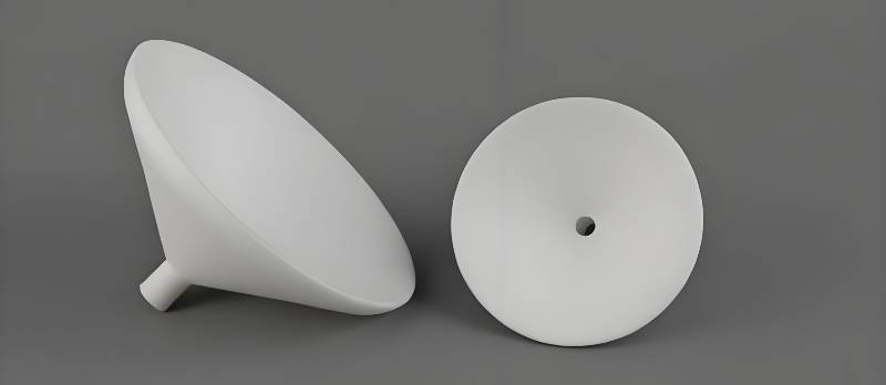
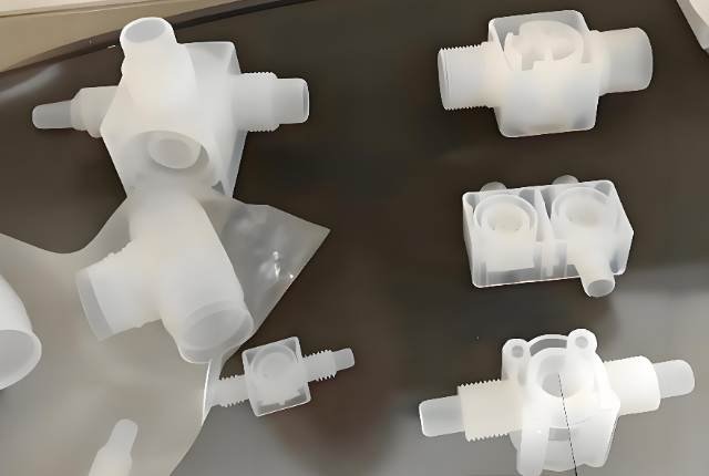
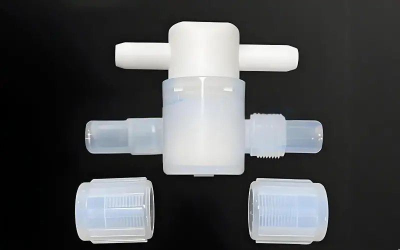
Seals, Liners & Valve Seats
PTFE is the standard material for valve seats, pump diaphragms, pipe liners, and gaskets in chemical plants handling acids, solvents, and oxidisers. Its near-universal chemical resistance eliminates compatibility assessment for most industrial chemicals.
- Pump impeller liners
- Reactor vessel seals
- Flanged joint gaskets
- Expansion joint liners
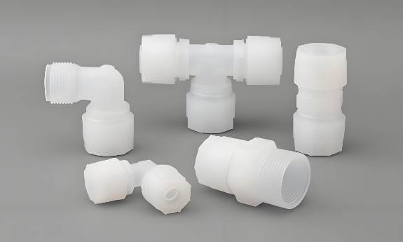
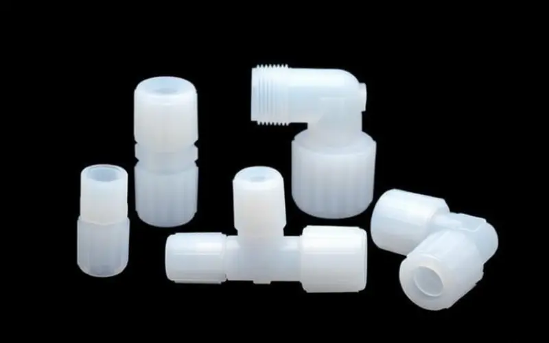
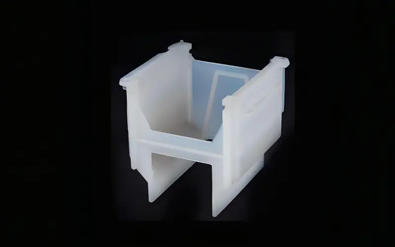
Ultra-Purity Fluid Handling & Insulation
Semiconductor fabrication demands materials that do not contaminate process chemicals or introduce ionic species into ultrapure water systems. PTFE's zero extractables profile and excellent dielectric strength (60 kV/mm) make it the default material for such applications.
- Wafer boats and carriers
- Chemical delivery fittings
- High-voltage spacers and insulators
- PCB drill guides
Implants & Sterile Fluid Paths
FDA 21 CFR 177.1550 compliant. PTFE is used in vascular grafts (ePTFE), catheter linings, surgical patches, and pharmaceutical process equipment. Its non-stick surface prevents biofilm accumulation and protein adhesion.
- Vascular graft tubing (ePTFE)
- Catheter shaft liners
- Pharmaceutical valve seals
Extreme-Temperature Components
PTFE maintains mechanical integrity from −200°C (cryogenic propellant systems) to +260°C (engine bay environments). Used for fuel system O-rings, hydraulic seals, and electrical wire insulation where thermal cycling would crack organic rubbers.
- Cryogenic valve seals
- Engine bay wire insulation
- Hydraulic actuator seals
Non-Stick & Hygienic Contact Surfaces
FDA-compliant, non-stick, easy to clean, and thermally stable through CIP/SIP sterilisation cycles. PTFE liners, conveyor components, and baking release surfaces meet 21 CFR 177.1550 for direct food contact at temperatures from freezer to oven.
- Conveyor belt release surfaces
- Baking release liners
- Food valve seats and diaphragms
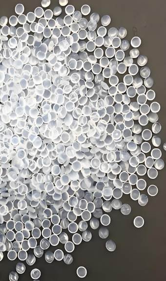
Self-Lubricating Bearings & Wear Parts
PTFE bearings run without external lubrication — a critical advantage in environments where grease contamination is unacceptable. Pure PTFE bearings are filled with glass fibre, carbon, bronze, or graphite to increase load-bearing capacity and reduce cold flow.
- Filled PTFE bushings (GF, carbon, bronze)
- Slide plates and pads
- Wear-strip linings
- Piston rings
Electrical Insulation & Cable Components
PTFE wire insulation maintains dielectric strength and dimensional stability at elevated temperatures where PVC and polyethylene degrade. Used extensively in aerospace wiring, high-voltage cable assemblies, and RF coaxial connectors where signal integrity depends on consistent dielectric properties across temperature extremes.
- RF coaxial insulation (PTFE/FEP)
- High-temperature wire jacketing
- Transformer insulation components
Advanced fluoropolymer components for critical industrial applications
What We Bring to
Fluoropolymer Parts Production
PTFE processing is not a capability most injection molders want to advertise — it requires different equipment, different sintering expertise, and a candid conversation about what the process can and cannot achieve. That conversation starts here.
PTFE & Teflon Injection Molding — Answered
The questions asked most often, answered directly.
Yes. PTFE complies with FDA 21 CFR 177.1550 for articles in contact with food. PFA and FEP comply under the same regulation. For medical applications, PTFE's non-reactivity and non-porosity make it suitable for fluid-path components, implant linings, and pharmaceutical process equipment. Medical-grade PTFE programs run under our ISO 13485:2016 QMS with full lot documentation.
Teflon is a registered trademark of Chemours (formerly DuPont) covering a range of fluoropolymers, of which PTFE (polytetrafluoroethylene) is the most common. In manufacturing, the terms are used interchangeably. Both refer to the —(CF₂—CF₂)n— polymer with the same coefficient of friction (0.04), service temperature (−200 to +260°C), and near-universal chemical resistance.
PTFE shrinkage is 2–5% — significantly higher than most engineering thermoplastics. Exact shrinkage depends on grade, part geometry, wall thickness, and sintering parameters. We calculate shrinkage compensation per part geometry at DFM and document it in the mold design record. Thin-walled parts shrink differently than thick-walled sections — uniform wall thickness is the most effective design control.
Would like to discuss PTFE & Teflon injection molding needs?
Our expert engineers can analyze your application requirements and recommend the optimal solution.


