
Custom Gas Assist Injection Molding Services
Gas assist injection molding injects pressurized nitrogen gas into molten plastic. The gas creates hollow sections while the material is still pliable. Cycle times drop significantly compared to traditional methods. Part quality improves dramatically with fewer sink marks and warping issues.
Our engineering team specializes in gas-assisted molding solutions. We help you reduce costs, improve quality, and accelerate production timelines with proven expertise.
ISO 9001:2015 Certified Processes
ISO 13485: 2016 Medical Device
AS9100 Quality Management
ISO 45001: 2018 Certified
In-Process Inspection with CMM
Gas-Assisted Injection Molding
Standard injection molding fills a mold cavity completely with molten plastic. Gas-assisted injection molding combines traditional injection techniques with controlled gas injection.
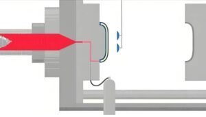
The process injects a partial shot of plastic material first. Then pressurized nitrogen gas enters through specialized nozzles.The nitrogen gas creates pathways through the molten material. These pathways form hollow sections within the part structure. The gas pressure also packs the plastic against the mold walls. This ensures excellent surface quality and dimensional accuracy.
Gas assist injection molding solves problems that plague traditional molding. Thick-walled parts often develop sink marks as material cools unevenly. Gas injection eliminates this issue by hollowing out thick sections.
Traditional Injection Molding
Traditional methods fill the entire mold cavity with plastic. Large volumes of material create cooling challenges. Thick sections cool slowly and often develop internal stresses.
These stresses lead to visible defects on part surfaces. Warping occurs as different sections contract at different rates. Long cycle times are required to ensure complete cooling throughout the part.
Gas-Assisted Injection Molding
Gas injection creates hollow sections that reduce material volume. Less material means faster, more uniform cooling. The gas pressure maintains part dimensions as plastic solidifies.
Parts emerge with smooth surfaces free from sink marks. Structural integrity improves because internal stresses are minimized. Cycle times decrease substantially, boosting production efficiency.
Internal vs. External Gas Assisted Injection Molding
Gas-assisted injection molding employs two distinct approaches as follow:
Internal Gas Injection Method
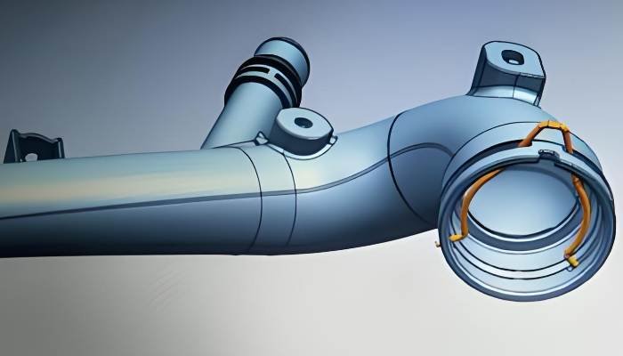
Internal gas injection introduces nitrogen directly into the molten plastic. The gas flows through the part’s interior, creating hollow channels. This approach works best for parts with tubular sections or thick ribs.
The process begins when plastic fills 70-95% of the mold cavity. Gas injection starts immediately afterward. The pressurized nitrogen penetrates the plastic, following the path of least resistance toward thicker sections.
Internal channels form naturally as gas displaces still-molten material. The gas pressure maintains until the plastic solidifies completely. This ensures the cavity remains properly packed and dimensional accuracy is preserved.
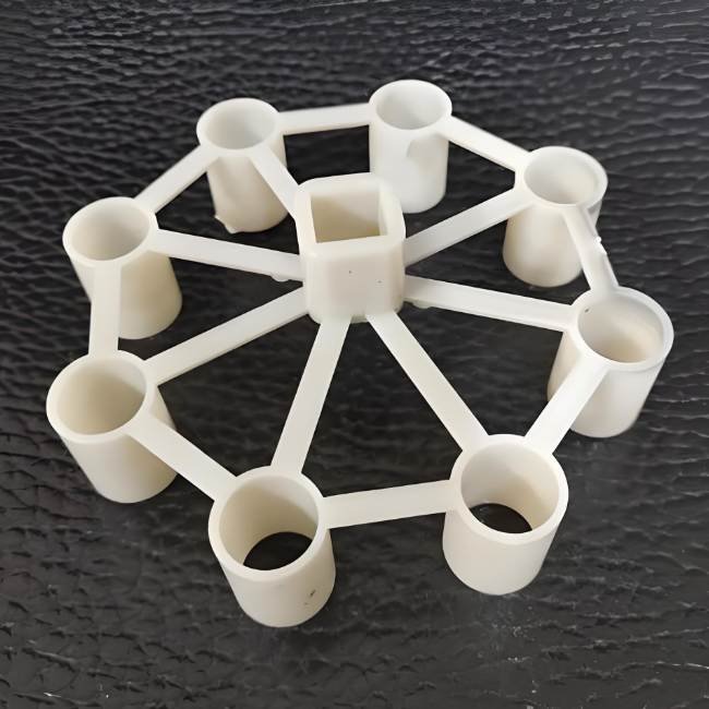
- Creates internal hollow sections that reduce weight significantly
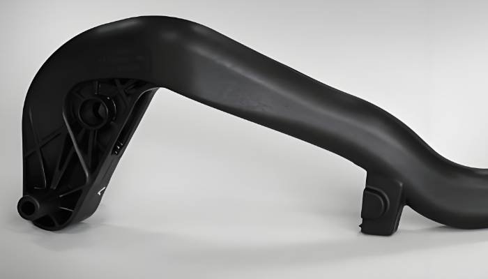
- Ideal for handles, tubular structures, and thick-walled components
- Eliminates sink marks in thick sections by hollowing from within
- Reduces material consumption by 25-40% in suitable applications
- Requires careful gas channel design to control gas flow paths
External Gas Injection Method
External gas injection places nitrogen between the part surface and the mold wall. The gas creates a thin layer that improves surface quality. This technique excels for large, flat parts prone to warping.
The mold fills completely with plastic material first. Then gas injects into specific areas between the plastic and mold surface. The gas pressure creates a slight gap that allows controlled shrinkage.
Surface quality improves dramatically with this approach. The gas cushion prevents the plastic from sticking to the mold. This eliminates surface imperfections and reduces the need for secondary finishing operations
- Improves surface finish on large, flat components
- Prevents warping in panels and broad surfaces
- Reduces cooling time by allowing air gap formation
- Eliminates witness marks and surface defects
- Works well with parts requiring Class A surface quality
The choice affects tooling design significantly. Internal gas injection requires specialized nozzles integrated into the mold. External methods need carefully designed gas pockets and venting systems. Both approaches demand precise process parameter control.
Some complex parts benefit from combining both approaches. Hybrid techniques use internal channels in thick sections while applying external gas to broad surfaces.
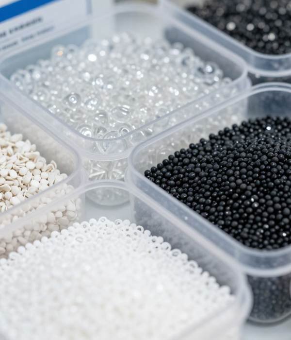
Materials Used in Gas-Assisted Injection Molding
Gas-assisted injection molding works with a wide range of thermoplastic materials.
Engineering Thermoplastics
- Polycarbonate stands out for optical clarity and impact resistance.
- ABS provides excellent processability and surface finish. The material flows easily and accepts gas injection readily.
- Nylon materials offer outstanding strength and wear resistance.
- Glass-filled nylon grades achieve exceptional rigidity. These materials suit structural components requiring durability under stress.
Commodity Plastics
- Polypropylene provides chemical resistance and flexibility.
- High-density polyethylene offers toughness and moisture resistance. Applications include containers, handles, and outdoor equipment. The process creates lightweight yet durable components.
Specialty and High-Performance Materials
- PEEK withstands temperatures up to 250°C continuously. The material resists chemicals and radiation. Aerospace and medical implant applications justify the higher material costs.
- PPS offers outstanding chemical and heat resistance. Gas assist processing maintains structural integrity while reducing weight.
| Material | Key Properties | Typical Applications | Gas Assist Suitability |
| Polycarbonate (PC) | High impact strength, optical clarity, heat resistance to 135°C | Automotive lighting, medical devices, safety equipment | Excellent – maintains clarity in hollow sections |
| ABS | Good impact resistance, excellent surface finish, easy processing | Consumer electronics, automotive trim, appliances | Excellent – superior flow characteristics |
| Nylon (PA) | High strength, wear resistance, chemical resistance | Structural components, gears, industrial parts | Very good – glass-filled grades perform well |
| Polypropylene (PP) | Chemical resistance, flexibility, low cost | Automotive interiors, packaging, consumer goods | Good – cost-effective for large parts |
| PC/ABS Blend | Combined benefits of PC and ABS, excellent impact at temperature extremes | Automotive exterior, power tools, outdoor equipment | Excellent – balances strength and processability |
| TPE (Thermoplastic Elastomer) | Rubber-like flexibility, soft touch, recyclable | Grips, seals, soft-touch components | Moderate – requires careful process control |
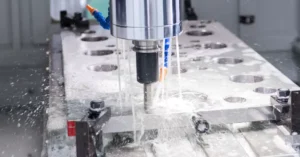
Gas Assist Injection Molding Process
Mold Preparation and Closing
The mold closes under high clamping force to prevent separation during injection. Temperature control systems bring the mold to optimal processing temperature.

Plastic Injection Phase
Molten plastic injects into the cavity at high pressure. The injection stops when the cavity reaches 70-95% full.

Gas Injection Phase
Nitrogen gas injects immediately after plastic injection ceases. Gas pressure typically ranges from 1,000 to 3,000 PSI depending on part size and material.

Packing and Holding Phase
Gas pressure maintains throughout the packing phase. This pressure compensates for plastic shrinkage as cooling begins.

Cooling Phase
The plastic solidifies while gas pressure continues. Cooling channels in the mold extract heat from the plastic. The hollow sections created by gas cool from both inside and outside surfaces.

Gas Evacuation and Part Ejection
Gas vents from the part once plastic achieves sufficient strength. The mold opens and ejector pins push the part free.

Process Efficiency
Modern two-shot injection molding machines complete full cycles in 30-90 seconds depending on part size and complexity. This represents significant time savings compared to manufacturing and assembling separate components.
Design Considerations for Gas Assist Injection Molding
Successful offers tremendous benefits, but only when designs accommodate gas flow principles. These considerations ensure optimal results.
- Wall Thickness and Gas Channel
- Gas Injection Point Location
- Rib and Boss Design
- Draft Angles and Surface Finish
- Complex Geometries and Undercuts
- Tolerance and Dimensional Control
Wall thickness critically affects gas flow behavior. The gas naturally migrates toward thicker sections where plastic remains molten longer. Designers intentionally create thicker areas where hollow sections are desired.
Uniform wall thickness throughout a part limits gas assist benefits. Varying wall thickness guides gas flow predictably. Transition zones between thick and thin sections require gradual changes to prevent stress concentrations.
Minimum wall thickness depends on material selection and part size. Most applications work well with walls between 2.5mm and 6mm. Thinner sections may not allow adequate gas penetration. Thicker sections increase cooling time unnecessarily.
- Maintain wall thickness ratios of 2:1 or 3:1 between thick and thin sections
- Design gas channels at least 1.5 times thicker than adjacent walls
- Avoid sudden thickness changes that disrupt gas flow
- Place thickest sections where structural strength is needed most
Gas injection point placement determines how effectively the process works. Entry points must align with desired gas flow paths. Poor placement causes incomplete gas penetration or surface defects.
Multiple injection points suit large or complex parts. Each point creates a separate gas channel. The channels should not intersect, as this causes unpredictable flow patterns.
Injection points leave small witness marks on part surfaces. Strategic placement hides these marks in non-visible areas. Handles, undersides, and assembly interfaces work well for gas entry locations.
Ribs provide structural reinforcement in molded parts. Traditional molding limits rib thickness to prevent sink marks. Gas-assisted molding eliminates this restriction completely.
Ribs can be thicker than adjacent walls when gas hollows them internally. This creates lightweight structures with exceptional stiffness. The hollow ribs maintain strength while reducing overall part weight.
Boss design benefits similarly from gas assist techniques. Thick bosses for screws or inserts typically cause sink marks. Gas injection hollows the boss core, eliminating surface defects while maintaining fastening strength.
Gas-assisted injection molding removes traditional constraints, enabling innovative designs that optimize performance and reduce costs.
- Ribs can exceed wall thickness without defects
- Hollow sections eliminate sink marks completely
- Lightweight structures maintain high stiffness
- Part consolidation reduces assembly operations
Draft angles facilitate part ejection from the mold. Gas-assisted parts require standard draft angles, typically 1-3 degrees per side. Deeper hollow sections may need slightly more draft for reliable ejection.
Surface finish quality depends on mold surface texture and processing conditions. Gas-assisted parts achieve excellent surface quality on external surfaces. Internal surfaces in gas channels show texture from the gas flow path.
Texture selection affects part appearance and functionality. Smooth textures suit visible surfaces and sliding contact areas. Textured finishes hide minor imperfections and provide better grip surfaces.
Gas assist enables complex geometries difficult with traditional methods. Curved tubes, varying cross-sections, and integrated features become feasible. The gas follows the designed path through intricate shapes.
Undercuts still require side actions or collapsing cores. Gas injection does not eliminate the need for proper mold design. However, internal undercuts in gas channels may be acceptable depending on part flexibility.
Gas-assisted parts maintain tight tolerances when designed properly. The gas pressure ensures consistent packing against mold walls. This produces repeatable dimensions across production runs.
Critical dimensions should be located on external surfaces in contact with the mold. Internal hollow sections show more variation than solid walls. Design features requiring tight tolerances accordingly.
Shrinkage compensation follows standard molding practices with some modifications. Gas-assisted parts typically show less shrinkage than solid parts of equivalent size. Material selection and wall thickness influence shrinkage rates significantly.
vs. Traditional Plastic Injection Molding
Advantages of Gas Assist Injection Molding
Gas-assisted injection molding delivers substantial advantages over traditional injection processes. These benefits span cost reduction, quality improvement, and design flexibility.
Material Cost Reduction
Hollow sections reduce material consumption by 25-40% in typical applications. The cost impact multiplies with expensive engineering plastics. High-volume production magnifies these savings across millions of parts. Reduced material usage also lowers shipping costs.
Elimination of Surface Defects
Gas injection eliminates sink marks by hollowing thick sections from within. External surfaces remain smooth and defect-free. This eliminates costly secondary operations like filling, sanding, or painting to hide defects. Parts achieve Class A surface finish directly from the mold.
Reduced Cycle Times
Cycle time reductions of 20-50% are common with gas-assisted molding. Hollow sections cool faster than solid material of equivalent thickness. The gas creates internal surface area that accelerates heat extraction. Shorter cycles also reduce energy consumption.
Improved Part Strength and Stiffness
The gas creates geometric shapes that resist bending and twisting. Structural integrity often improves compared to solid sections of the same weight. The uniform cooling prevents internal stresses that cause delayed failure. Thicker walls become feasible without defects.
Enhanced Design Flexibility
Part consolidation becomes practical with gas assist technology. Multiple components can merge into single parts. This reduces assembly operations, eliminates fasteners, and improves reliability. Varying cross-sections, integrated handles, and structural ribs all work well.
Lower Clamping Force Requirements
Large, thick-walled parts require massive, expensive molds for traditional molding to withstand enormous clamping forces and injection pressures. Gas assist injection reduces the clamping force. Lower injection pressures allow lighter mold construction. The cost savings on tooling can be substantial for large parts.
Industries Considering Gas-Assisted Injection Molding
Medical Device
Handles for surgical instruments
Diagnostic equipment housings
Patient care devices
Laboratory equipment
Consumer Goods and Electronics
Television and monitor bezels
Power tool housings
Appliance panels
Appliance components like refrigerator door liners
Sports & Recreational Equipment
Bicycle frame components
Exercise equipment frames and handles
Recreational vehicle components
Plastic grandstand seats
FAQs About Gas-Assisted Injection Molding
Gas assist works effectively across a wide size range. Small parts under 50 grams benefit when thick sections require hollow cores. Large parts exceeding 5 kilograms show dramatic material and cost savings.
The technology proves most economical for parts with dimensions exceeding 150mm in any direction. Smaller parts may not justify the additional tooling complexity unless high volumes warrant automation benefits.
Yes, gas-assisted parts maintain tight tolerances on external surfaces. The gas pressure packs plastic firmly against mold walls, ensuring dimensional consistency. External dimensions typically achieve ±0.1mm or better depending on material and part size.
Internal hollow sections show more variation than external surfaces. Design critical dimensions on mold-contact surfaces whenever possible. Proper process control delivers repeatability matching traditional injection molding.
Yes, multi-cavity molds work well with gas assist technology. Each cavity requires independent gas injection control for consistent results.
Balanced gas distribution ensures all cavities produce identical parts. Process monitoring verifies consistent gas penetration across all cavities. Multi-cavity tooling maximizes production efficiency for high-volume applications.
Yes, recycled materials process successfully with gas assist techniques. Material flow characteristics and gas penetration behavior remain consistent when using quality regrind. Typical regrind content ranges from 10-25% depending on performance requirements.
Most gas-assisted parts require minimal secondary operations. The excellent surface quality eliminates finishing steps needed for traditional molded parts. Some applications require trimming of overflow material or finishing of injection point witness marks.
Ready to Transform Your Manufacturing?
Our experienced team is ready to evaluate your application and provide detailed cost analysis. Discover how gas-assisted injection molding can transform your manufacturing efficiency and product quality.
Products Gallery


Transform Your Manufacturing with Gas-Assisted Technology
Join industry leaders who have reduced costs, improved quality, and accelerated production with gas-assisted injection molding.
Our proven solutions deliver measurable results.
Related Resources

Design for Injection Molding: Guidelines and Tips& Defect Solutions
Master design for injection molding with our comprehensive guide: 10 core guidelines, tooling tips, and solutions for common defects—optimize part quality, reduce costs, and boost efficiency.
Water Assisted Injection Molding: How WAIM Works, Benefits, and Industrial Applications
Learn how Water Assisted Injection Molding works, the benefits, materials, and industrial applications for faster, lighter, and high-precision production.
What Is Gas Assist Injection Molding? A Complete Process Guide
Gas assisted injection molding uses nitrogen at 2,000–4,500 psi to create hollow cores, cut material use by 20–40%, and eliminate sink marks. Process guide with parameters.