
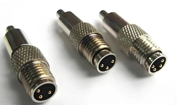
| An electrical connector is a device that joins electrical conductors to form a circuit, enabling power or signal transfer between two or more points in an electronic system. Every connector consists of at minimum two functional elements: one or more conductive contacts that carry current or signal, and an insulating housing that positions those contacts correctly, protects them from the environment, and enables reliable mating and unmating. |
Connector design varies enormously with application — a low-force ZIF connector for a smartphone display has almost nothing in common with a sealed circular connector on an aircraft nacelle, yet both perform the same fundamental function. What differentiates them is the operating current and voltage, the number of mating cycles required, the temperature and vibration environment, and the regulatory certifications the application demands.
This guide covers the main components of electrical connectors, the specific materials and coatings used in each, the four-stage manufacturing process, environmental protection ratings, and the criteria that govern connector selection in demanding applications.
What are Electrical Connectors?
An electrical connector creates a separable or permanent junction between two electrical conductors. Separable connectors — USB ports, automotive connectors, modular jacks — allow repeated connection and disconnection over the device’s service life. Permanent connectors — soldered or crimped wire terminations — are designed for a single connection that will not be disturbed during normal service.
The distinction between permanent and separable connections matters for material selection. A separable contact must withstand hundreds to tens of thousands of mating cycles without measurable contact resistance increase. A permanent termination needs to be highly solderable or crimpable, but durability under repeated mechanical engagement is not a primary requirement.
Core Functional Requirements of Every Connector
Low and stable contact resistance: Any increase in contact resistance generates heat under load (P = I²R) and can cause thermal failure. High-quality signal connectors specify contact resistance below 10 mΩ; power connectors typically specify below 1 mΩ.
Environmental isolation: The insulating housing must prevent current leakage between adjacent contacts (creepage and clearance distances per IEC 60664-1) and exclude moisture, dust, and chemical contaminants per the application’s IP rating.
Mechanical durability: Contacts must maintain adequate normal force and contact area through the rated number of mating cycles. Reduced normal force increases contact resistance; lost contact altogether produces an open circuit.
Common Applications by Industry
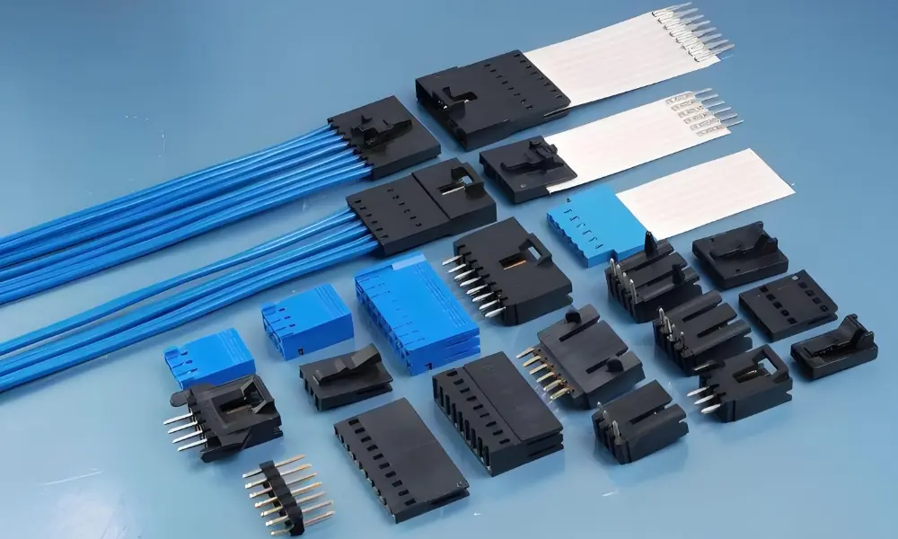
Connectors appear in every industry where electricity is used, but the engineering requirements differ substantially by sector:
- Automotive: Connectors face operating temperatures from −40°C to 125°C (extended to 150°C near the engine), vibration environments per USCAR-2 or LV214, and 25–30 year service life expectations for body electronics.
- Aerospace: Circular connectors per MIL-DTL-38999 or ARINC 600 specifications operate at altitude (low atmospheric pressure increases corona discharge risk), high vibration, and extreme temperature ranges from −65°C to +200°C.
- Medical devices: Connectors in patient-contact equipment must be sterilisable (EtO, autoclave, gamma per application), biocompatible, and meet IEC 60601-1 electrical safety requirements for body-contact isolation voltages.
- Consumer electronics: USB4 Gen 3 connectors handle 40 Gbps data and 240 W power (USB PD 3.1) through the same physical interface — contact geometry and plating must support both simultaneously without impedance mismatch.
- Industrial: M12 and M8 circular connectors dominate factory automation and fieldbus networks. IP67 and IP68 ratings are standard. Connectors must survive chemical splash, pressure washdown, and continuous vibration in proximity to rotating machinery.
Main Components of Electrical Connectors
A production connector integrates four distinct component groups: the housing, the contacts, the terminals (wire interface), and the insulation and sealing system. Each is engineered and manufactured separately before assembly. Below, we’ll look at each major part.
1. Connector Housings
Connector housings are the framework for the entire connector assembly. These enclosures provide structural support and ensure all internal parts stay properly aligned and protected. They are more than just passive shells – they actively contribute to performance and durability.
The housing performs four simultaneous functions: it electrically isolates adjacent contacts to prevent short circuits, physically positions contacts at the correct pitch and depth for reliable mating, protects the contact assembly from mechanical damage, and provides the mechanical interface (latches, threads, bayonet lugs) that holds mated connectors together under vibration.
Housing geometry comes in two primary forms. Rectangular housings (PCB headers, wire-to-board connectors, DIN rail terminal blocks) are efficient to populate on printed circuit boards and simple to stack at high contact density. Circular housings (MIL-38999, M12, M8, XLR audio) are geometrically easier to seal and more resistant to accidental mating-plane misalignment — advantages that make circular formats standard in rugged and waterproof applications.
Housing Materials — Engineering Selection Guide
The housing material determines operating temperature range, chemical resistance, flammability rating, and the minimum wall section achievable in injection moulding. For connector applications, UL 94 V-0 flammability certification (the highest flammability rating under UL 94) is the standard baseline — connectors in electrical equipment must not sustain combustion after ignition.
| Material | Class | Key Properties | Typical Connector Application |
| PBT (Polybutylene terephthalate) | Thermoplastic | 94V-0 flammability, excellent dimensional stability, low moisture absorption < 0.08% | Automotive connector housings (e.g., engine bay, ABS modules), industrial controls — tolerates repeated mating cycles without warping |
| PPS (Polyphenylene sulfide) | Thermoplastic | Continuous service to 200–220°C, exceptional chemical resistance, 94V-0 | High-temperature underhood automotive connectors, aerospace sensor housings, chemical processing equipment |
| LCP (Liquid Crystal Polymer) | Thermoplastic | Miniaturisation leader — wall sections to 0.2 mm possible, 94V-0, very low warpage | Micro-pitch connectors in smartphones, hearing aids, implantable devices; 0.3–0.5 mm pitch board-to-board |
| PA66 / PA46 (Polyamide) | Thermoplastic | Good toughness, widely qualified, lower cost than PPS — moisture absorption 2.5–3.5% requires pre-drying | Consumer electronics, telecom, low-cost industrial connectors where absolute dimensional precision is secondary |
| Aluminium alloy (e.g., 6061-T6) | Metal | High strength, excellent EMI shielding, thermal conductivity 167 W/(m·K), corrosion-resistant | Military circular connectors (MIL-DTL-38999), aerospace rack-and-panel, industrial DIN housings |
| Stainless steel (304 / 316) | Metal | Highest corrosion resistance, suitable for sterilisation — autoclave, EtO, gamma-compatible | Medical device connectors (ECG, catheter lab systems), food-processing equipment, subsea/offshore applications |
| Alumina ceramic (Al₂O₃) | Ceramic | Withstands > 1,500°C, dielectric strength > 10 kV/mm, hermetic when metallised | High-voltage feedthroughs, thermocouple connectors, hermetically sealed implantable device connectors |
LCP (Liquid Crystal Polymer) deserves special attention. Its combination of very low viscosity at processing temperature and extremely low post-moulding shrinkage (< 0.1%) allows housing walls as thin as 0.2 mm — critical for the micro-pitch board-to-board connectors used in smartphones, hearing aids, and wearable medical devices.
Environmental Protection — IP Ratings in Practice
IP (Ingress Protection) ratings per IEC 60529 specify the degree of protection the assembled connector provides against solid particles and liquids. [1] The first digit (1–6) rates solid particle exclusion; the second digit (1–9K) rates liquid ingress.
| IP Rating | Protection Level | Engineering Implications for Connector Housing Design |
| IP54 | Dust protected / Splash water | General industrial panels, handheld equipment. Housings must close without parting-line gaps > 0.3 mm. Foam or rubber gasket compresses 15–25%. |
| IP65 | Dust tight / Low-pressure water jets | Outdoor controls, HVAC equipment. All cable entries gland-sealed. No unsealed vent holes. Housing wall deflection under jet pressure must not break gasket contact. |
| IP67 | Dust tight / 1 m immersion, 30 min | Portable field instruments, automotive sealed connectors. O-ring groove width ±0.10 mm for consistent compression. Parting line shutoff < 0.05 mm gap. |
| IP68 | Dust tight / Defined depth, long term | Subsea sensors, military connectors. Depth and duration specified by manufacturer. Hermetic glass-to-metal or ceramic-to-metal sealing used for permanent/critical connections. |
| IP69K | Dust tight / High-pressure/temp water spray | Food processing, agricultural, dairy washdown equipment. Must withstand 80°C water at 80–100 bar. Silicone or EPDM seals required — standard NBR degrades at 80°C. |
2. Connector Contacts
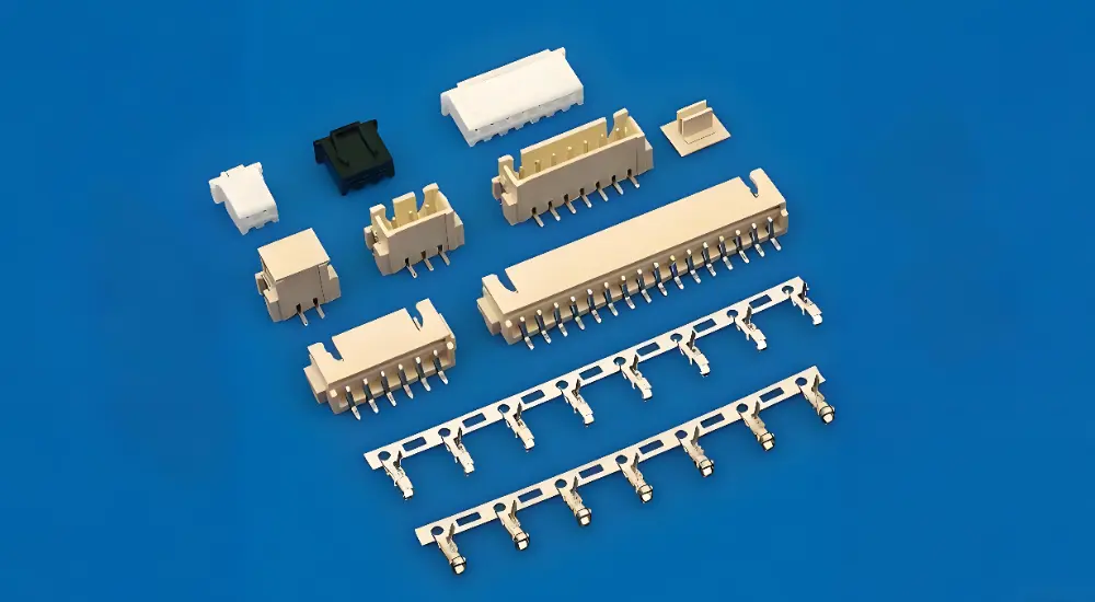
Contacts are the conductive elements that carry current or signal across the mating interface. They must maintain a defined contact force throughout the rated mating cycle life — because contact resistance scales inversely with contact area and contact force, any spring relaxation or wear that reduces normal force increases resistance.
Contact geometry falls into four main types:
- Pin and socket (male/female): The universal form. Male pins insert into female sockets that exert a radial spring force on the pin. Contact force typically 50–300 g depending on current rating and cycle-life requirement.
- Blade contacts: Flat, wide contacts for high-current applications (busbars, EV battery packs). Large contact area allows current density to remain low even at hundreds of amperes.
- Pogo pins (spring-loaded contacts): A spring-loaded plunger in a cylindrical barrel. Used for battery charging contacts, test interfaces, and dock connectors that require easy engagement with no insertion force. Stroke length typically 1–4 mm.
- Hyperboloid contacts: An array of helically wound wires forming a barrel-shaped cage. The pin engages multiple wire contacts simultaneously — achieving high contact reliability under vibration and shock. Standard in aerospace and military applications.
Contact Base Materials
Copper alloys form the base of virtually all electrical contacts because copper’s conductivity (5.96 × 10⁷ S/m) is second only to silver among common metals.
- Phosphor bronze (Cu-Sn-P): High spring strength and good fatigue resistance — the standard contact material where the contact arm acts as a spring leaf. Conductivity ~15% IACS (International Annealed Copper Standard) — lower than brass but stiffer.
- Brass (Cu-Zn alloys, C26000): Better conductivity than phosphor bronze (~28% IACS) and easier to machine. Used for pin contacts where dimensional precision and high conductivity matter more than spring stiffness.
- Beryllium copper (BeCu, C17200): Highest spring performance of any copper alloy — 220–250 HV hardness. Used for high-cycle-life contacts (> 10,000 matings) in high-reliability applications. Requires special handling during fabrication due to Be powder toxicity.
Contact Surface Plating — Performance Data
Copper alloys oxidise quickly in ambient air, forming a resistive copper oxide layer. All production contacts receive a surface plating to prevent oxidation, control contact resistance, and manage fretting wear over mating cycles.
| Plating Material | Thickness | Key Performance Characteristics | Primary Application |
| Gold (Au) | 0.1–1.0 µm | Lowest contact resistance (< 10 mΩ typical), no oxidation, 30+ year shelf life | Signal-level connectors (< 1 A), precision instruments, mil-spec contacts per MIL-DTL-55302 |
| Palladium-Nickel (PdNi, ~80/20) | 0.1–0.5 µm | Harder than gold (HV 450–500 vs gold HV 100), lower cost, good fretting resistance | Telecom and data-comm connectors: QSFP, SFP, SIM cards — balances cost and durability |
| Silver (Ag) | 2–10 µm | Highest bulk electrical conductivity (6.3 × 10⁷ S/m), excellent for high-current contacts | High-power connectors (> 100 A), bus bars, EV battery connectors, relay contacts |
| Tin (Sn) / Tin-lead | 1–5 µm | Solderable, low cost, contact resistance < 5 mΩ when fresh — tarnishes over time, prone to fretting | PCB edge connectors, low-cost wire-to-board, consumer electronics where replacement is viable |
| Nickel (Ni) underlayer | 1–3 µm (base) | Diffusion barrier between copper substrate and final finish — prevents copper migration to surface | Standard underlayer beneath gold or tin on all copper-alloy contact substrates |
The nickel underlayer is not optional. Copper diffuses rapidly through gold plating at elevated temperatures — at 125°C, copper migration to the gold surface begins within weeks, forming a resistive copper oxide film under the gold. A 1–3 µm nickel barrier layer between the copper substrate and the final gold finish prevents this diffusion and is standard practice for contacts that will see elevated temperatures or long service lives. [3]
3. Connector Terminals
Terminals are the wire interface elements that connect the external conductor (wire or cable) to the connector’s internal contact system. The terminal must form a gas-tight joint with the wire — any oxidation-permeable gap between conductor strands and terminal will develop increased resistance over time.
Three termination methods are used in production:
Screw / IDC (insulation displacement): Screw terminals clamp the wire mechanically — standard in field-wired terminal blocks for easy maintenance. IDC (insulation displacement) terminals pierce wire insulation with sharp tines, displacing it to contact the conductor — fast, tooling-free, and suitable for low-current telecommunications applications.prevent corrosion. Quality checks throughout production. Sensors and camera vision systems check dimensions.
Crimp termination: A crimping tool deforms the terminal barrel around the stripped wire strands, cold-welding the barrel to the conductor under compressive force. Correctly executed crimp joints are gas-tight, vibration-resistant, and the fastest termination method in automated wire harness production. Pull-out force specifications (e.g., 22 N minimum for 0.5 mm² wire per IPC/WHMA-A-620) validate crimp quality. [2]
Solder termination: The stripped wire is inserted into a cup or barrel terminal and soldered. Produces a secure joint with excellent electrical performance but is sensitive to solder voids, cold joints, and is not preferred in high-vibration environments where thermal cycling can crack the solder.
4. Insulation and Sealing
Insulation within the connector housing prevents current leakage between adjacent contacts (creepage) and prevents arcing across gaps under voltage (clearance). IEC 60664-1 defines the minimum creepage and clearance distances required for a given working voltage, pollution degree, and overvoltage category.
Material selection for insulation depends on operating temperature, chemical environment, and whether the connector is moulded as one piece or assembled from discrete insulator wafers. High-performance thermosets — phenolic resins, epoxy — are used where continuous service temperatures above 150°C are required, as thermoplastics generally soften at these temperatures.
Sealing materials require careful specification for chemical compatibility with the service environment. Silicone rubber seals perform from −60°C to +200°C and are the standard choice for most sealed connectors. EPDM is preferred in UV-exposed outdoor applications. Nitrile (NBR) is the default for fuel-system connectors in automotive applications. Fluorosilicone (FVMQ) is used where both fuel resistance and low-temperature flexibility (−55°C) are required simultaneously.
Additional Features in Electrical Connectors
Electrical connectors often come with extra features to make them more reliable and easier to use. These features protect the connections, prevent errors and ensure everything fits together correctly.
Strain Reliefs and Cable Glands
Strain reliefs protect the termination point — the most mechanically vulnerable location on any connector — from axial pull, lateral bending, and torsional load. Without strain relief, repeated cable movement concentrates all bending stress at the crimp or solder joint, causing fatigue failure in the conductor strands over time.
Overmoulded strain reliefs (the outer boot on most cable-mounted connectors) are produced by two-shot injection moulding or secondary overmoulding. They bond directly to the cable jacket and taper in stiffness away from the connector body — a graduated transition that distributes bending load over the cable length rather than concentrating it at a single point.
Keying and Polarisation
Keying prevents incorrect mating of connectors that share the same physical form factor. In a multi-connector panel where several identical connectors carry different voltages or signal types, keying ensures that a connector intended for 48 V cannot be inserted into a 5 V socket — preventing damage or safety hazards that might not be immediately visible.
Polarisation ensures directional alignment during mating — the connector can only engage in one rotational orientation. This is particularly important for blind-mate applications (where the operator cannot see the mating interface during engagement) and for power connectors where reverse polarity would damage connected equipment.
EMI Shielding
Shielded connectors reduce electromagnetic interference (EMI) emissions from high-frequency signals and protect sensitive circuits from external radiated EMI. The shield must provide a continuous low-impedance path from the cable shield to the equipment chassis ground — any gap or high-impedance bond in this path creates an antenna that radiates or receives unwanted signals.
Shield termination methods — 360° circumferential crimp, braid clamp, or conductive overmould — affect the shield transfer impedance (ZT), the key metric for shield performance. A ZT below 10 mΩ/m at frequencies up to 100 MHz is the target for most high-speed data connector shielding requirements.
How Electrical Connectors Are Manufactured
Connector production follows four sequential stages: stamping, plating, injection moulding, and assembly. Each stage feeds directly into the next; production is typically organised as a continuous flow from coil stock to finished connector assembly.
Stage 1 — Stamping
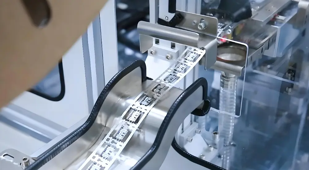
Contact and terminal fabrication begins with progressive die stamping. A metal strip (typically phosphor bronze or brass, 0.1–0.8 mm thick) feeds from a coil through a multi-station progressive die at 200–800 strokes per minute. Each station performs a specific cut, pierce, or forming operation; the fully formed contacts emerge on a carrier strip — still attached in sequence — ready for the plating stage.
Progressive die stamping achieves tolerances of ±0.01–0.03 mm on contact dimensions at high production rates. Contact width, spring arm geometry, and contact depth — all of which directly affect contact resistance and insertion force — are established in the stamping stage. A vision system downstream of the press checks critical dimensions at 100% of production, typically inspecting 50–200 features per contact at rates above 600 parts per minute.
Stage 2 — Electroplating
After stamping, the contact strip moves to the plating line. Plating is almost always barrel plating (for small, discrete contacts) or reel-to-reel plating (for contacts still on the carrier strip, which preserves contact geometry and allows precise selective plating of contact areas only).
The plating sequence for a gold-plated contact is: electrolytic cleaning → strike nickel (thin adhesion layer) → barrier nickel (1–3 µm) → selective gold on contact surfaces only (0.1–0.5 µm for commercial connectors, 0.5–1.25 µm for mil-spec). Selective plating — applying gold only to the contact area and not the full contact body — reduces gold consumption by 40–70% and is standard in high-volume production.
Quality issues unique to the plating stage — surface pinholes, plating voids, thin spots, and edge burning — are among the most difficult to detect by automated vision inspection because connector surface geometry creates reflection artefacts. Destructive cross-section analysis and X-ray fluorescence (XRF) thickness measurement are the primary quality verification methods for plating conformance.
Stage 3 — Injection Molding
Connector housing molding uses the same process principles as any precision injection molding — but with tighter requirements. A 0.3 mm pitch board-to-board connector housing requires cavity features machined to ±0.005 mm tolerance. Flash on the contact retention features that would prevent pin insertion must be controlled to less than 0.05 mm.
Engineering thermoplastics used in connector housings — PBT at 250°C barrel temperature, PPS at 310–330°C, LCP at 300–320°C — require hot runner systems to prevent gate freeze-off at fine features and multi-cavity tooling with individually balanced runners to maintain equal fill across all cavities.
Post-moulding inspection uses transmitted backlight to identify internal voids, incomplete fill (short shots), and clogged contact retention sockets — defects that are invisible from external visual inspection but would prevent contact insertion during assembly.
Stage 4 — Assembly
Final assembly inserts the plated contacts into the molded housing. For small connectors, this is done by automated insertion machines that handle individual contacts from vibratory feeders and press each into its housing pocket to a defined depth and locking engagement. For complex multi-piece connectors, sub-assembly sequences build up the connector in stages.
Assembly inspection verifies two critical parameters: that every contact pocket is populated (no missing pins) and that each contact is seated to the correct depth. High-speed vision systems check both parameters simultaneously at rates above 50 connectors per second in automated production lines.
Overmolded connectors — where a cable-connector assembly is placed in a secondary mold and encapsulated in a protective jacket — are produced as a final sub-assembly step, sealing the wire-to-terminal interface against moisture and mechanical stress before the connector ships.
How to Select the Right Electrical Connector
Connector selection is a constraint satisfaction problem — the chosen connector must simultaneously satisfy electrical, mechanical, environmental, regulatory, and cost constraints. Relaxing any single constraint may invalidate the entire selection.
Electrical Parameters
Current rating: Defined as the maximum continuous current per contact at a specified temperature rise (typically 30°C above ambient). Derating applies at elevated ambient temperature — a connector rated for 10 A at 25°C may be limited to 6–7 A at 85°C ambient.
Voltage rating: Determined by creepage and clearance distances between adjacent contacts, which in turn are defined by the insulating material and the working voltage per IEC 60664-1. Increasing voltage rating requires either increasing contact pitch or improving the dielectric properties of the insulating material.
Signal integrity: For high-speed differential signals (USB 3.x, PCIe, HDMI), impedance control (50 Ω or 100 Ω differential) is critical. Contact geometry, dielectric material, and contact pitch all affect characteristic impedance. At frequencies above 10 GHz, connector performance is typically characterized by insertion loss and return loss, not DC contact resistance.
Environmental and Mechanical Requirements
Temperature range: Confirm that both the housing material (with its HDT/continuous service temperature) and the contact plating remain within specification across the full operating temperature range, including post-solder reflow temperatures if the connector is board-mounted.
Mating cycles: Connectors are rated for a defined number of mating cycles — typically 30 (crimp terminals), 500 (board-to-wire), 5,000 (USB-A), or 10,000+ (mil-spec). Contact resistance must remain within specification after the full rated cycle count. Exceeding the rated cycle life is a design error, not a manufacturing deficiency.
IP/sealing requirement: Match the system IP rating to the application environment. Specifying IP67 for an indoor control panel that will never see liquid adds cost without benefit. Specifying IP54 for outdoor marine equipment that will see spray and immersion is a field failure waiting to happen.
Regulatory Certifications
Verify that the connector holds all certifications required for the target market. UL/CSA approval is required for electrical equipment sold in North America. CE marking (compliance with Low Voltage Directive or Machinery Directive) is required for the EU. REACH and RoHS compliance is required for all electrical equipment sold in the EU and most other markets. MIL-SPEC connectors must meet the specific MIL-DTL designation called out in the equipment specification.
Certification to one standard does not imply certification to another. A connector with UL 94 V-0 housing material is not automatically IP67 rated. A MIL-DTL-38999 connector is not automatically RoHS-compliant in its standard form (some mil-spec finishes use cadmium, which is restricted under RoHS). Each certification must be explicitly verified on the component datasheet.
Custom Connector Manufacturing
Standard cataloge connectors satisfy the majority of applications. Custom connectors are warranted when: a unique combination of contact count, pitch, and orientation is required; a specific IP or environmental rating is needed that standard designs do not achieve; the application demands a material not available in standard designs (e.g., all-stainless for autoclave sterilisation); or volume economics justify tooling investment in a proprietary design.
Custom connector programs start with a detailed specification: current and voltage per contact, operating temperature range, mating cycle requirement, IP rating, applicable certifications, housing material preference, and target unit cost. The engineering design phase translates these into material selections, contact geometry, plating specification, and housing dimensional drawings before any tooling investment is made.
Manufacturers with in-house CNC machining, stamping tooling, and injection mold capabilities compress the development timeline by eliminating tooling lead times between stages. An overmolded cable assembly — combining stamped contacts, injection-molded housing, and overmolded cable seal — can be prototyped in 4–6 weeks from design approval when all capabilities are co-located.
→ Related: Fecision connector mold manufacturing capabilities
Frequently Asked Questions
What is the difference between gold and tin contact plating?
Gold plating (0.1–1.0 µm) provides the lowest and most stable contact resistance — typically below 10 mΩ — with no oxidation over a 30+ year service life. It is the standard for low-voltage signal contacts, precision instruments, and military/aerospace connectors where contact reliability is critical. Gold is expensive; selective plating on the contact area only reduces material consumption.
Tin plating (1–5 µm) is far less expensive, solderable (important for PCB edge connectors), and provides adequate performance in many consumer and commercial applications. However, tin oxidises over time increasing contact resistance, is prone to fretting corrosion under vibration, and tin whisker growth is a known reliability concern for some tin alloy formulations. Tin-plated contacts are not recommended for high-cycle or vibration-critical applications.
What is contact resistance and why does it matter?
Contact resistance is the electrical resistance at the mating interface between two contacts. It adds to the circuit’s total impedance and generates heat under current (P = I²R).
Contact resistance increases with: surface oxidation (addressed by gold or palladium-nickel plating), reduced contact force (caused by spring relaxation over mating cycles or high temperature), contamination or fretting wear debris at the contact interface, and reduced contact area (from misalignment or geometric wear). Connector specifications define maximum contact resistance both initially and after the rated number of mating cycles — ensuring the connector meets its resistance budget across its full service life.
Conclusion
Knowing the components of electrical connectors is key to choosing the right products and system success. From connector housings that shield and align to connector contacts and terminals that provide the electrical path, each part is critical to performance and durability.
Working with experienced electrical connector manufacturers ensures product reliability and access to custom solutions. Their mold making and CNC machining services enable fast innovation and customization for your application. As electronic systems become more complex and demanding, the once-overlooked connector plays an increasingly vital role. Whether you’re sourcing components, designing circuits or maintaining infrastructure, knowing your connectors inside out can make all the difference.
References & Authoritative Sources
Accessed April 2026.
[1] IEC 60529:1989+AMD1:1999+AMD2:2013. Degrees of protection provided by enclosures (IP Code). International Electrotechnical Commission. https://webstore.iec.ch/publication/2452
[2] IPC/WHMA-A-620E. Requirements and Acceptance for Cable and Wire Harness Assemblies. IPC — Association Connecting Electronics Industries. https://shop.ipc.org/ipc-whma-a-620/ipc-whma-a-620e-english-pdf-0-0
[3] MIL-DTL-55302. Detail Specification: Connectors, Printed Circuit, Miniature, Polarized, Electrical. US Department of Defense. https://lmipubs.lmi.org/