Cooling often takes a big slice of your injection molding cycle time. If temperatures aren’t consistent, you could face common problems like part warpage, sink marks, and unwanted stress. Saving just one reliable second in this phase directly reduces unit production costs. This efficiency also lets you boost cavitation without needing extra press hours.
This guide will explain conformal cooling in injection molding, how its channels are designed, and why it outperforms traditional drilling. You will discover where this thermal advantage brings the biggest gains, helping you achieve measurable results in your high-volume programs.
What Is Conformal Cooling?
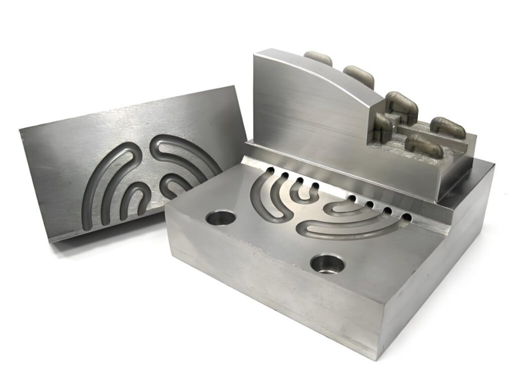
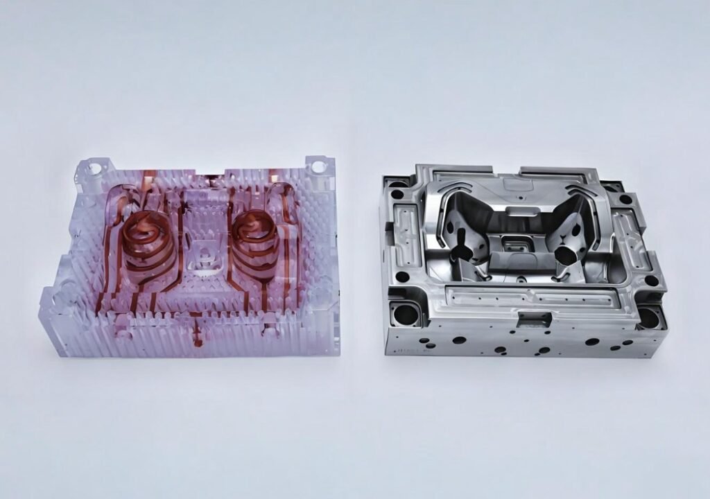
Conformal cooling channels are cooling paths that curve and closely follow the exact shape of your molded part. These channels maintain a nearly constant gap to the mold cavity wall. This design is what ensures heat is removed uniformly from your component, especially from very thick or hard-to-reach areas.
So what is conformal cooling? This term refers to the entire technique of integrating these specially shaped channels into your injection molds. They are used to replace or significantly improve the less efficient, straight-drilled cooling circuits. The core process that makes these complex internal shapes possible allows for structures like internal helices or manifolds that are impossible to create using conventional machining methods.
Because these channels are able to bend and curve in three-dimensional space, they can smartly route around essential mold components. They can easily dodge ejector pins, lifters, and parting-line bolts. This flexible design allows you to maintain the ideal, tight center-line-to-wall distance required for truly effective and uniform cooling.
Benefits & Drawbacks of Conformal Cooling
Before choosing this technology, you need to compare the possible benefits with the practical problems. We will start by looking at the strong advantages this method offers for your production line.
Benefits
Conformal cooling delivers faster cycles, tighter quality, lower energy, and extended mold life, offering freedom for complex part designs.
Noticeable Cycle-Time Reduction
Most tools that use this method see a 15-40% drop in the overall cooling time. This time saving is a huge advantage for you. It means you can produce more parts every single shift without having to buy any expensive new capital equipment.
Tighter Temperature Spread
Channel conformity ensures the temperature across your mold’s cavity face stays within just a few degrees Celsius. This tighter temperature control greatly reduces defects like warpage and sink marks. This, in turn, helps you achieve a higher Cpk on your most critical part dimensions.
Lower Energy Demand per Shot
The combination of a shorter clamp phase and reduced time needed for water circulation helps you trim your kilowatt-hour (kWh) usage. This energy saving not only lowers your operating costs but also helps you support your company’s internal sustainability reporting goals.
Extended Mold Life
When the metal temperature stays uniform, the mold experiences less thermal fatigue over time. This gentle cooling helps critical features like the parting lines and shut-offs remain intact and highly effective over extremely long and demanding production runs.
Freedom for Complex Geometry
Designers gain significant freedom because they can effectively cool difficult areas. You can now cool behind threads, follow complex curves, and reach thin ribs without being limited by drilling. This opens up the door to designing parts that are much lighter and more intricate.
Conformal Cooling vs Conventional Cooling Benefits
| Metric | Conformal Cooling | Conventional Drilling |
| Typical cycle improvement | 15–40% reduction | Baseline |
| Temperature spread | Several °C tighter | Wider delta |
| Channel geometry & precision | 3D paths, consistent distance to cavity | Straight-line only, fixed depth |
| Routing round hardware | Yes | Seldom practical |
| Up-front insert cost | Moderately higher | Baseline |
| Economic Payback | Justified at high production volumes | Cost-effective standard for most projects |
Drawbacks
The benefits are clear, but you must be realistic about the process. Here are some key limits and the higher initial costs you need to include in your plan.
Longer Front-End Engineering
This advanced technique requires more time at the beginning of the project. You must perform iterative Computational Fluid Dynamics (CFD) and extensive channel optimization. Choosing the right build orientation for 3D printing adds days to the design phase compared with simple straight-line drilling.
Build-Envelope Limits
The largest insert you can make is limited by the size of the 3D printer platform. If your tools are very large, like those for car or appliance parts, you may have to use segmented inserts. This means extra assembly work when building the mold.
Higher Insert Cost
The initial investment is typically higher than a standard drilled plate. This is due to the cost of DMLS powder, the slower build rates of the 3D printing process, and the necessary post-print heat treatment. Therefore, justifying this higher spend usually requires that your production volumes are medium to high.
Powder or Support Removal in Small Channels
Long, highly curved passages that are smaller than 5 mm in diameter can sometimes trap unmelted powder or supporting structures. To prevent this, manufacturers must include special flush ports and maintain very clean-room coolant practices during mold testing and operation.
Potential for Channel Scaling
The intricate internal features of the channels may lead to problems if you neglect water treatment. Flow can be restricted, or the channel walls may thin due to erosion or scale buildup. This neglect could eventually cause leaks or create unwanted hot spots on the mold surface.
How Conformal Cooling Works
Understanding the sequence of steps, from digital design to final production, is crucial. This is a multi-stage process that leverages advanced simulation and additive manufacturing.
Step 1 – Design & Simulation
The first step is incorporating the three-dimensional channel paths directly into the CAD models. Then, CFD software is used to predict the wall temperature distribution and the pressure drop in the system. Finite Element Analysis (FEA) is also run to check the mold insert’s deflection under the strong clamp force. This allows for iterative refinement before any metal is actually melted.
Step 2 – Additive Build (DMLS)
Once the design is fully optimized, the insert is grown layer-by-layer in a powdered material. Common materials include tool steel, copper alloy, or stainless steel. This Direct Metal Laser Sintering (DMLS) process creates internal features like helices, manifolds, or complex bubbler feeds that would be completely inaccessible using conventional machining methods.
Step 3 – Post-Processing & Quality Control
After the print, several crucial steps are taken. This includes removing internal support structures and performing stress-relief heat treatment. A vacuum-tight leak test is mandatory to ensure integrity. Finally, the cavity surface undergoes final polishing to meet both the required SPI finish and long-term lifetime standards.
Step 4 – Integration & Commissioning
The finished insert is then carefully fitted into the existing A and B plates of the mold base. Thermocouples and flow meters are installed and mapped to your press controller for real-time monitoring. A short-shot Design of Experiments (DOE) run is performed to confirm the actual cycle-time savings compared to your initial baseline data.
Step 5 – Production Monitoring & Maintenance
To guarantee long-term performance, always use clean, filtered coolant. You should also do regular reverse-pulse flushing and check the channel flow often. This collected production data is extremely valuable for improving your next conformal cooling design.
Need expert help launching your conformal cooling mold? Discuss your project specifications with Fecision today.
Tips on Designing Effective Conformal Cooling Channels
When you start the design phase, you must consider both practical manufacturing limits and your thermal cooling goals. Following these five tips will help you create a cooling circuit that works very effectively.
Maintain Practical Channel-to-Wall Distance
If the channel is too close to the surface, you risk a cooling channel breakout. If it’s too far, you lose cooling power. Iterative FEA (Finite Element Analysis) is the key tool for finding the exact, balanced gap needed for every feature, like a rib or a boss, for the best heat transfer.
Quick Reference: Channel Spacing Guidelines
While detailed simulation is the gold standard, the following table provides a good starting point. These values are based on common industry practice and successful cooling benchmarks. Always validate these figures against your specific part geometry and material properties.
| Product Wall Thickness | Recommended Channel Diameter | Channel Center-to-Center Spacing | Minimum Distance from Channel Center to Cavity Surface |
| ~2 mm | 8 – 10 mm | 25 – 40 mm | 15 – 30 mm |
| ~4 mm | 10 – 12 mm | 30 – 50 mm | 20 – 35 mm |
| ~6 mm | 12 – 15 mm | 35 – 60 mm | 25 – 45 mm |
Consider Oval Profiles for Thin-Wall Regions
Using an oval-shaped channel is often better in very thin-wall areas. An oval profile maximizes the total surface area available for cooling. Importantly, it still allows for adequate steel width to be maintained between the channel and the surface to handle the necessary rated pressure.
Serial vs Parallel Loops
Serial flow paths are simpler to seal but result in a higher temperature difference of the coolant. Parallel manifolds are generally better for balancing the flow. You use orifice inserts here to ensure every single cavity sees a very similar inlet temperature, which is essential for high-cavitation medical molds.
Keep Pressure Drop in Check
Aiming for a moderate loop pressure drop is key, as this helps to reduce the load on your cooling pump. Only add complex helical or very restrictive sections when your modeling and simulation work clearly shows a worthwhile gain in your heat-flux removal rate.
Orient the Build for Powder Evacuation
When preparing for the DMLS print, tilting the insert inside the chamber is important. This orientation prevents channels that face downwards from getting closed off. You must also strategically plan access ports so that any residual powder can be fully flushed out before you perform the final plug-weld.
Post-Print Heat Treatment & Polishing
Standard age-hardening cycles are used to achieve the necessary strength in the metal. This is then followed by intensive cavity polishing. This polishing brings the surface to an optical-grade Ra finish, which is necessary for reproducing a high-gloss look on parts like lens housings or clear covers.
Where Conformal Cooling Delivers Maximum Value
Conformal cooling injection molding truly shines where complex part shape, material, and high volume meet a critical challenge. The core idea is simple: it allows you to control heat with surgical precision to deliver uncompromising quality at the fastest commercial speed. Let’s look at five industries where this technique delivers the best ROI.
Automotive Interior Trim
For large, talc-filled panels with a high-quality Class-A surface, conformal cooling has demonstrated a clear cycle-time reduction and significantly fewer paint-sink rejects. This translates into measurable cost savings per shot, especially on high-volume production programs.
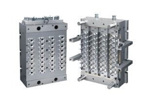
Medical Pipette Tips
In high-cavitation molds used for thin-wall pipette tips, this cooling method keeps the tip straightness within extremely tight tolerances. This precision has led to a marked increase in the automated-inspection pass rate, which is a big gain for you.
Consumer Electronics Housings
The uniform cooling of frames made from PC+ABS material has been shown to cut part warpage by more than half. This is crucial for meeting the micro-gap specifications required for effective, water-resistant gasket sealing in modern electronics.
Thin-Wall Packaging Caps
A flip-top closure part, when produced on a stack mold with conformal cooling, ran noticeably faster without experiencing any ovality drift. This enhanced speed allowed the manufacturer to add hundreds of thousands of parts per month to their existing press capacity.
Aerospace Ductwork
For a carbon-loaded PEEK wave-guide, specialized copper-alloy inserts were used to efficiently pull heat away from critical hot spots. This advanced heat management was necessary for meeting very strict porosity limits without requiring multiple time-consuming design iterations.
Conclusion
Conformal cooling in injection molding is a proven method you can use to significantly shorten your cycle time, consistently lift your part quality, and effectively trim your unit energy consumption. This technology gives you a major thermal advantage in high-volume production.
Fecision delivers superior injection molding results by leveraging advanced technology and deep expertise. Our focus on tight tolerances and fast cycle times works perfectly with the benefits of conformal cooling channels. We make sure your complex parts meet the highest quality standards quickly by combining precise mold making and strict quality checks.
Our commitment to quality and innovation is essential when using conformal cooling channels. We apply DFM analysis and in-process inspection (CMM) to validate designs that maximize the cooling efficiency, ensuring consistent part-to-part repeatability and significantly reduced material waste. This guarantees the full commercial advantage of high-speed injection molding.
Ready to start a project that demands high-precision, faster cycles, and reduced costs? Get a quote from our injection molding experts.