
PA6 GF30 Injection Molding: Housing 2-Cavity Hot Runner Mold
For special material - PA6 GF30% injection molding, let's see how Fecision team conducts professional DFM analysis to identify and solve the challenges.
Nylon Injection Molding
PA6 GF30% (Black)
Security & Access Solutions Industry

Specification
Project Overview
What did this project deliver?
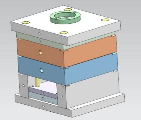
A 2-cavity injection mold for a glass-fiber reinforced PA6 housing with hot runner + cold sub gate, SKD61/S136 cavity steel, and 3-slider parting design. Inspection uses an OMM 2D&3D measuring system at ≤0.002 mm detection precision. One critical tolerance relaxation was identified and documented during DFM.
| Mold Type | 2-Plate Injection |
| Cavities | 2 Cavity |
| Mold Base | S50C |
| Cavity Steel | SKD61 / S136 |
| Core Steel | SKD11 |
| Gate System | Hot Runner + Sub Gate |
| Runner Config | 1 Hot Zone + Cold Sub |
| Sliders | 3 Sliders |
| Ejection | Sleeve + EJ Pin φ2.0 mm |
| EJ Pin Recess | Recess ≤ 0.05 mm |
| Shrinkage | 0.3 – 0.6% |
| Mold Dimensions | 400 × 300 × 360 mm |
| Machine | FANUC i100A (100 T) |
| Cavity Mark Sink | 0.1 mm/min |
| Inspection | OMM 2D&3D ≤ 0.002 mm |
Problem Diagnosis
Engineering Challenges Identified in DFM Review
Five structural and process risks were flagged during the mold structure review before any steel was ordered. Each item directly affects dimensional conformance, cycle reliability, or part quality on the production floor.

Tight Tolerance vs. PA6 GF30 Shrinkage
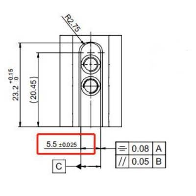
The drawing specifies 5.5 ±0.025 mm with flatness 0.08 A and parallelism 0.05 B on a feature that spans a significant length. Glass-fiber PA6 shrinks anisotropically — fiber alignment along the flow path reduces shrinkage in one direction while increasing it transversely.
With a shrinkage range of 0.3–0.6% and the part's overall length, holding ±0.025 mm post-mold is at the boundary of what injection tooling can reliably deliver without secondary machining.

Warpage Risk on Long Span Dimensions
Multiple dimensions are affected by both shrinkage variation and warpage — the two failure modes compound each other on glass-filled polyamide. When the part cools non-uniformly, differential shrinkage between GF-rich and GF-lean zones causes the part to bow.
Engineering response: Dimensions in the flagged zones were proposed for tolerance relaxation from drawing values to ±0.05 mm to match what the process can reliably deliver.

3-Slider Geometry — Parting Line Complexity
The housing geometry requires three sliders to release undercut features on three separate faces. Each slider introduces a parting seam — three seams meeting on a single part multiplies the flash risk and the precision requirement for slider-to-cavity contact alignment.
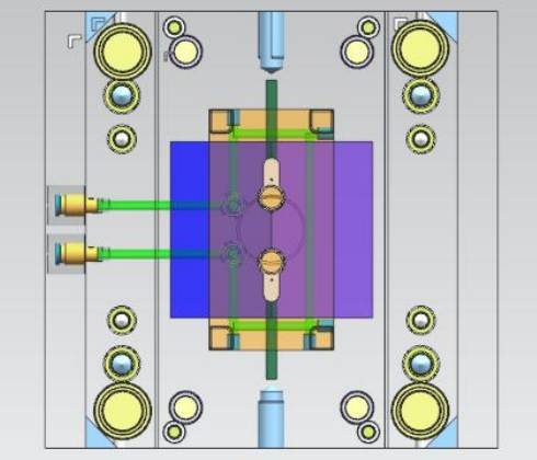
The main parting line runs at the mid-plane (red line, cavity front/core rear split). Slider PL seams at each side feature must all close to the same standard without leaving witness marks on functional surfaces.

Ejection System — Sleeve + Pin Configuration
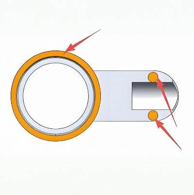
The cylindrical bore (Ø17 mm feature) requires a sleeve ejector rather than conventional ejector pins — a pin placed inside the bore would cause marking on a bore surface that mates with a locking cylinder component. The remaining ejector positions use EP φ2.0 mm pins at the flat base.
The critical constraint: ejector pin positions must be flush or recessed ≤0.05 mm — any protrusion above the part face is a rejection criterion because the housing seats against a precision assembly interface.
EJ protrusion: 0 mm (flush) to −0.05 mm only

Draft Angle — Minimal Undersize Relief Required
Draft analysis identified two surface categories: green-zone surfaces (most of the part exterior) require material removal of less than 0.05 mm per side to achieve clean draft without affecting critical dimensions. Pink-zone surfaces (the bore interior and two slider-facing faces) require even tighter relief — less than 0.03 mm per side.
These limits mean the cavity polishing operation must be controlled at sub-tenth-of-millimeter scale to avoid over-cutting draft that is intended to be minimal for dimensional retention.
Mold Engineering Solution
The design selected a 2-plate mold with hot runner + cold sub-gate configuration. The hot runner (1 heated zone) keeps the PA6 GF30 melt at injection temperature from machine to manifold, eliminating cold runner waste. A cold sub-gate (submarine gate) then delivers the melt through the parting surface in a way that auto-separates from the part on mold opening — no manual degating operation required per cycle.
Steel selection was deliberate: SKD61 for the primary cavity faces (H13 equivalent, hot-work tool steel, excellent thermal fatigue resistance under PA6's high processing temperature of 260–290°C) and S136 for the secondary cavity inserts that require higher corrosion resistance. The SKD11 core (D2 equivalent, high wear resistance) protects the internal bore geometry that is contacted by the sleeve ejector every cycle.
For full injection mold technical specifications, see our injection mold capabilities →
- ✓ Hot runner (1 zone) feeds cold sub-gate — zero cold runner waste, automatic degating
- ✓ SKD61/S136 cavity + SKD11 core — material matched to PA6 GF30 thermal and wear demands
- ✓ 3-slider mechanism releases all undercut features without secondary operations
- ✓ Sleeve ejector on Ø17 bore + EP φ2.0 pins on flat base — no mark on functional surfaces
- ✓ OMM 2D&3D inspection at ≤0.002 mm precision — all drawing positions covered
- ✓ DFM-flagged tolerance zones relaxed to ±0.05 mm with client concurrence
3D Geometry Review
Part 155.372 received. DFM scope defined. Drawing D000471237-000 (approved 2022-02-01) used as tolerance reference.
Gate & Runner Design
Hot runner (1 zone) + cold sub-gate selected. Gate entry point on top face evaluated against flow balance to 2 cavities.
Parting Line Definition
Main PL at mid-plane (red line). 3 slider PL seams defined for 行位 1/2/3 features on three separate faces.
Draft Analysis
Green zones: <0.05 mm/side material removal. Pink zones (bore + slider faces): <0.03 mm/side. Cavity polish controlled accordingly.
DFM Report Issued
8 mold structure items documented. Critical: tolerance relaxation request on shrinkage-affected dimensions. Client sign-off required.
Steel Procurement & Machining
S50C base, SKD61+S136 cavity inserts, SKD11 core. 400×300×360 mm mold envelope on FANUC i100A press.
T1 Sample + OMM Inspection
All drawing positions measured on OMM 2D&3D system at ≤0.002 mm precision. Dimensional report delivered with first article.
Manufacturing Strategy & Inspection
Fecision conducts a formal product risk assessment at the start of every new program. The assessment covers environmental compliance, application classification, and body-contact status — these three factors determine which material certifications, process controls, and traceability requirements apply.
Steel Selection Strategy
Three distinct steels for three functional zones.
▲ S50C mold base — structural, cost-effective, sufficient for a 100T press.
▲ SKD61 primary cavity — H13 class, chosen for thermal shock resistance under repeated PA6 GF30 shots at 270–290°C barrel temperature.
▲ SKD11 core — D2 class, for wear resistance against abrasive glass fibers on the bore surface that contacts the sleeve ejector 200,000+ cycles.
Gate Location & Runner Design
The hot runner nozzle enters the top face of the part geometry.
A single heated zone maintains PA6 melt temperature to the manifold.
The sub-gate (submarine/tunnel gate) auto-shears on ejection — this eliminates a manual degating step that would otherwise add 3–5 seconds to every cycle.
Cooling Channel Routing
Cooling circuit runs through both the cavity (front mold) and core (rear mold) blocks. Two inlet/outlet pairs feeding the cavity block from the side, with internal channels arranged to maintain even temperature distribution across the cylindrical bore region — the thickest wall section and therefore the longest cooling zone.
Uniform cooling in the bore prevents differential shrinkage that would distort the Ø17 mm feature beyond its tolerance.
Inspection Protocol — OMM 2D&3D
Key dimensional positions are inspected using the VMS-3020 OMM measuring system at detection precision ≤0.002 mm. Both 2D (projected contour) and 3D (surface point cloud) modes are used — 2D for the bore diameters and thread features, 3D for the curved exterior housing surfaces where flatness and parallelism callouts apply.
Cavity number is marked on the part at 0.1 mm/min sink depth to allow traceability without affecting the part's seating surface.
Dimensional Performance
& Process Metrics
Quantitative outputs from the DFM review and mold structure analysis. Where the DFM proposed changes versus the original drawing, both values are shown. "Before" = original drawing requirement; "After/Proposed" = DFM-recommended or confirmed process capability.
| Parameter | Drawing / Original | DFM / Proposed | Direction |
|---|---|---|---|
| Tab width tolerance (5.5 mm feature) | ±0.025 mm | ±0.025 mm (monitored) | — Hold, risk-flagged |
| Shrinkage-affected long dimensions | Per drawing (tight) | ±0.05 mm (proposed) | ↗ Relaxed for process reliability |
| Green-zone draft material removal | Not specified | <0.05 mm/side | ✓ Defined in DFM |
| Pink-zone draft material removal | Not specified | <0.03 mm/side | ✓ Tighter zone defined |
| EJ pin surface relationship | Flush (0 mm) | Recess 0 – -0.05 mm | ✓ Zero protrusion confirmed |
| Cavity number depth | Not specified | 0.1 mm/min | ✓ Standard established |
| Bore Ø17 diameter | Ø17 -0/-0.1 mm | Inspected by OMM 2D | ✓ In-process OMM verified |
| Thread M4×0.5 position | GD&T per drawing | OMM 3D surface scan | ✓ Position verified 3D |
| Inspection system precision | Standard CMM | VMS-3020 OMM ≤0.002 mm | ↗ Higher precision tool |
| Runner waste (hot runner system) | Cold runner (waste per shot) | Hot runner — near zero waste | ↗ Material saving per cycle |
5 Reusable Principles from the Project
These findings apply beyond this specific part number — they represent transferable principles for any glass-fiber filled polyamide injection mold with tight tolerance requirements and complex slider geometry.
Anisotropic Shrinkage Must Be Zoned, Not Averaged
GF30 polyamide does not shrink uniformly in all directions — fiber alignment along the flow path reduces shrinkage 30–50% versus the transverse direction. Applying a single shrinkage factor across an entire part leads to systematic dimensional errors. Zone the part by expected fiber orientation and apply direction-specific offsets to each cavity region.
Tolerance Relaxation Before Steel Cuts Cost Less Than ECN After T1
The DFM identified dimensions where the original ±0.025 mm tolerance was incompatible with the process capability of injection molding PA6 GF30. Proposing relaxation to ±0.05 mm during DFM — before any steel is ordered — costs zero. The same change raised as an engineering change notice after T1 carries steel rework cost, schedule delay, and a repeat first-article cycle.
Sub-Gate Auto-Shear Eliminates a Manual Labor Step Per Cycle
Choosing a submarine (sub) gate over a side gate or edge gate means the gate automatically shears during ejection. On a 2-cavity mold running at, say, 30-second cycles, eliminating a 4-second manual degating operation saves approximately 9,600 operator-seconds per 1,000 cycles. That compounds across millions of parts. Gate style is a productivity decision, not just a quality one.
Sleeve Ejectors Protect Bore Geometry From Ejection Marking
On a cylindrical bore that mates with a precision mechanical component, a conventional ejector pin placed on the bore face creates a raised witness mark every cycle. A sleeve ejector — a hollow cylinder that surrounds the core pin and lifts the part from the outside of the bore — distributes ejection force around the bore perimeter without creating a point mark. This is the correct choice whenever the bore seats against another precision part.
OMM Inspection at ≤0.002 mm Is Necessary for GD&T Callouts Below 0.05 mm
The housing drawing carries GD&T callouts including flatness 0.08 mm and parallelism 0.05 mm. To verify these with statistical confidence, the measurement system uncertainty must be at least 5× below the tolerance band. OMM at ≤0.002 mm satisfies this requirement for the 0.05 mm GD&T callout (ratio: 1:25). A conventional CMM at 0.01 mm accuracy would be marginal and unreliable for this application.
Your Success Story Could Be Next!
Want results like these for your own production?
Reach out — let’s talk about what we can achieve together.


