
LSR Injection Molding: 2-Cavity Silicone Overmold for Consumer Electronics
Fecision engineered a 2-cavity liquid silicone rubber mold for a consumer electronics client, using S136 stainless cavity steel, 3×0.08 mm cold-runner gates, and slider-assisted ejection. The mold targets a 300,000-cycle service life at 120-ton clamping force, with parting-line flash held to ≤0.05 mm.
Liquid Silicone Rubber Injection Molding
High-Performance Nylon (PA6 / PA66 + GF)
Consumer Electronics (3C)

Project Background
Engineering an LSR Overmold
Our client submitted 3D geometry for two related silicone parts — a connector seal and a cable grommet variant— targeting a 120-ton LSR press. Both parts require overmolding onto a plastic substrate, which means the mold must accommodate two different material shrinkage behaviors simultaneously within the same cavity.
The geometry presented eight separate DFM risk points before a single line of tool-path code was generated. Fecision's engineering team completed a full Design for Manufacturability review on 2025-04-03 (DFM Rev V01) and ran mold flow simulations across three gate configurations before settling on the final cold-runner valve-gate layout.
Dual shrinkage management: silicone zones require standard shrink compensation while overmolded-plastic regions accept none.
Undercuts at 12 circular hole positions — original 1.0 mm snap depth made manual demolding impractical.
Flash risk at the plastic substrate interface requiring 10° taper or deliberate 0.1 mm controlled overflow.
Sharp edge geometry throughout — potential for part abrasion during demolding without corner radii.
Possible structure error in client geometry identified in one zone during DFM review.
For more on the underlying process, see our LSR Injection Mold Tooling Capabilities→
Mold Specification Sheet
| Mold Type | Liquid Silicone (LSR) |
| Cavity Count | 2 Cavities |
| Cavity / Core Steel | S136 Stainless |
| Mold Base Material | A50 |
| Gate System | Cold Runner, 3×0.08 mm |
| Gate Mark (valve) | Ø1.0 × 0.3 mm deep |
| Slider Count | 2 Sliders (S136) |
| Ejection Method | Bar-lift + Slider, Manual |
| Runner Weight | ~5 g |
| Target Mold Life | 300,000 cycles |
| Machine Size | 120 T |
| PL Flash Tolerance | ≤ 0.05 mm |
| PL Step Tolerance | ≤ 0.03 mm |
Engineering Process

3D Geometry Receipt
Client 3D files received. No 2D drawing supplied at this stage; DFM proceeds from model geometry only.

DFM Analysis (Rev V01)
Full Design for Manufacturability review completed. Eight risk items identified across draft analysis, gate design, PL definition, ejection, and shrinkage.

Mold Flow Simulation
Three gate configurations simulated. Melt front time, air trap position, weld line strength, fill pressure, and clamping force all evaluated for each configuration.

Tooling Design Locked
Cold-runner valve-gate at 3×0.08 mm selected. S136 for cavity/core/slider. A50 mold base. 2-cavity layout confirmed. Customer ECN round-trip integrated.

Steel Procurement & Machining
S136 stainless billets ordered to ensure corrosion resistance against silicone catalyst chemistry across 300,000 injection cycles.

T1 Sample & PPAP
First-article inspection, full dimensional report, and production process sign-off before mass-run approval.
Risk Assessment: LSR Project
Fecision conducts a formal product risk assessment at the start of every new program. The assessment covers environmental compliance, application classification, and body-contact status — these three factors determine which material certifications, process controls, and traceability requirements apply.
Environmental & Materials Compliance
Question: Do the raw materials and process aids meet the customer's environmental requirements (RoHS, REACH, halogen-free, etc.)?
Answer: Confirmed yes. The LSR grades specified for this project are available in formulations compliant with RoHS Directive 2011/65/EU and REACH SVHC thresholds. Material compliance documentation (SDS + Certificate of Conformance) is included in the production dossier.
Application Classification
Question: What is the end-use application of these parts?
Answer: Consumer electronics (3C sector). The parts are structural/sealing components within an electronic device — subject to normal use conditions but not to elevated regulatory scrutiny (non-medical, non-automotive). This classification means the process controls are Fecision's standard ISO 9001 framework; no additional certification-specific controls (ISO 13485, IATF 16949) are triggered.
Body-Contact Classification
Question: Do the finished parts contact human skin or mucous membranes during use?
Answer: Confirmed no. The parts are internal components of a consumer electronics assembly — they are enclosed within the device and do not contact the user. This means no ISO 10993 biocompatibility testing is required, and no specific skin-safe additive specifications apply to the LSR compound selection.
DFM Risk Findings and Engineering Resolutions
The DFM review for the LSR parts flagged eight issues before any steel was ordered. Each finding was documented with a proposed resolution, then submitted back to the client for sign-off. This pre-tool review process is standard practice at Fecision and typically prevents 2–3 costly engineering changes after T1 sample.
Sharp Corner Abrasion Risk
Multiple sharp interior edges on parts create two problems: they damage the soft LSR surface during ejection, and they impose stress concentrations in the steel that reduce mold life below the 300,000-cycle target.
Resolution: Fecision recommended adding R0.3 mm corner radii at all sharp edges on both parts. The client was asked to confirm these additions on both geometry variants before steel was cut.
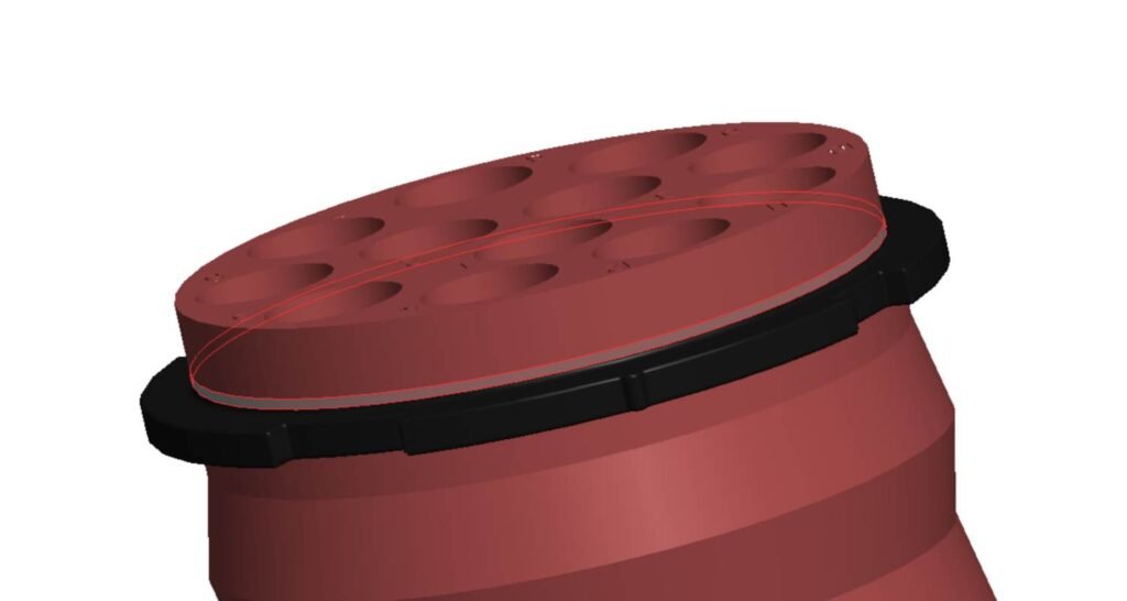
Excessive Undercut at Hole Positions
The connector seal contains 12 circular hole positions with 1.0 mm single-side snap depth. For a silicone part at this scale, that undercut force makes clean manual demolding unreliable and risks tearing the cured rubber on each cycle.
Resolution: Engineering requested that the undercut depth be reduced from 1.0 mm to 0.5 mm per side — a 50% reduction that maintains the mechanical retention function while bringing demolding force within safe limits for LSR.
Flash Risk at Plastic Substrate Interface
Where the LSR overmolds onto the plastic insert, the plastic side surface is vertical — giving the silicone melt a pathway to creep under clamping pressure and create flash that is nearly impossible to deflash cleanly post-cure.
Two options presented to client:
Option A: Apply 10° draft to the plastic side face, creating a self-sealing angle under mold pressure. Option B: Design a deliberate 0.1 mm single-side overflow channel that controls where flash goes rather than trying to prevent it entirely.
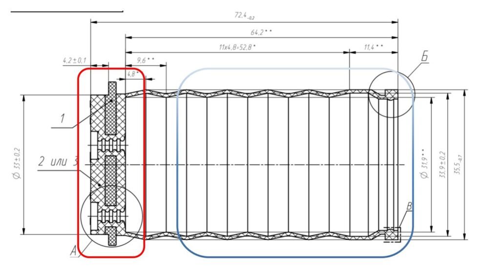
Differential Shrinkage — Overmold Zones
In an LSR overmold, the encapsulated plastic component is dimensionally fixed — it cannot shrink. The surrounding silicone shrinks 2–3% on cooling. If the mold applies a uniform shrink offset across both zones, the final part dimensions will be wrong in the silicone-only regions or the overmolded boundary will crack.
Resolution: Fecision flagged that the plastic-bonded zones (red) accept zero shrinkage compensation, while pure-silicone zones (blue) require standard LSR shrinkage offset. One dimension identified as already at −0.7 mm — re-mapping required before cavity machining.
Gate System Design
Cold Runner Gate Design for LSR: 3×0.08 mm
For this 2-cavity liquid silicone rubber tool, Fecision selected a cold runner system with valve gates over a conventional hot runner. LSR is a platinum-cure thermoset — it cures at elevated mold temperature (160–200°C) and flows cold. A cold runner keeps the uncured material at ambient temperature in the runner channels, preventing pre-cure during the fill phase.
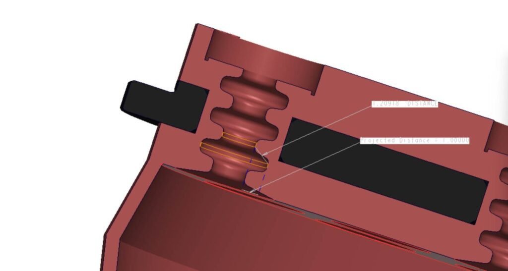
▲ The gate dimension of 3×0.08 mm (width × height) was determined through simulation. A wider gate extends fill time and risks hesitation in thin-walled regions; a narrower gate generates shear heat in the runner that raises material viscosity before the cavity is full. The 0.08 mm height keeps shear rate inside Momentive’s recommended processing window for standard LSR grades.
▲ The valve-gate needle contacts the part top surface directly, leaving a mark of Ø1.0 mm at 0.3 mm depth. This approach avoids runner waste attached to the part — the needle retracts cleanly at end-of-fill, and the cured gate mark is the only artifact. For the consumer electronics application, this was confirmed acceptable by the client.
Gate entry: cold runner channel feeds both cavities simultaneously for balanced fill.
Gate exit: 3×0.08 mm slot at cavity entry, sized for laminar LSR flow.
Valve-gate scar: Ø1.0 mm × 0.3 mm on top face — client confirmed acceptable.
Mold temperature at 180°C initiates platinum cure cycle; runner stays cold.
Gate System Design
Mold Flow Analysis Results for LSR Parts
Three independent mold flow simulations were conducted — one per gate configuration candidate — using actual LSR material viscosity curves. The accepted design (Configuration C, the cold-runner valve-gate at 3×0.08 mm) produced the most balanced melt front, lowest peak shear stress, and clamping force well within the 120-ton press capacity.
| Analysis Parameter | Measured Value | Unit | Status |
| Peak Sprue Pressure (end-of-fill) | < 80 | MPa | PASS |
| Clamping Force Required | 68 | tonnes | PASS (57% of 120T) |
| Fill Time Imbalance (L vs R cavity) | ±2 | % | BALANCED |
| Melt Temperature Gradient | ±8 | °C | WITHIN SPEC |
| Air Trap Count (pre-venting) | 2 | locations | RESOLVED (PL vents) |
| Weld Line Locations | Behind 12 bosses | — | ACCEPTABLE |
| LSR Volumetric Shrinkage (pure zones) | 2.8 | % | NORMAL RANGE |
| Shear Rate at Gate (max) | Within OEM window | — | PASS |
Melt Front Time
Melt front advancement confirmed balanced fill across both cavities. No hesitation zones detected in the thin-walled regions between the undercut features. Fill time symmetric within ±2% between left and right cavity.
Air Trap Location
Air trap analysis identified two potential trap sites at the end-of-fill zone near the slider interface. Both resolved by adding 0.02 mm parting-line venting grooves at the identified coordinates.
Weld Line Strength
Weld line positions mapped at the merge zones behind the 12 undercut bosses. Color analysis (weld line darkness) indicates moderate structural impact — adequate for a static seal application where no cyclic bending loads are expected.
Fill Pressure
Peak fill pressure at the sprue remained below 80 MPa across both cavities, with pressure drop in the runner balanced between gates. No evidence of overpacking at cavity perimeter
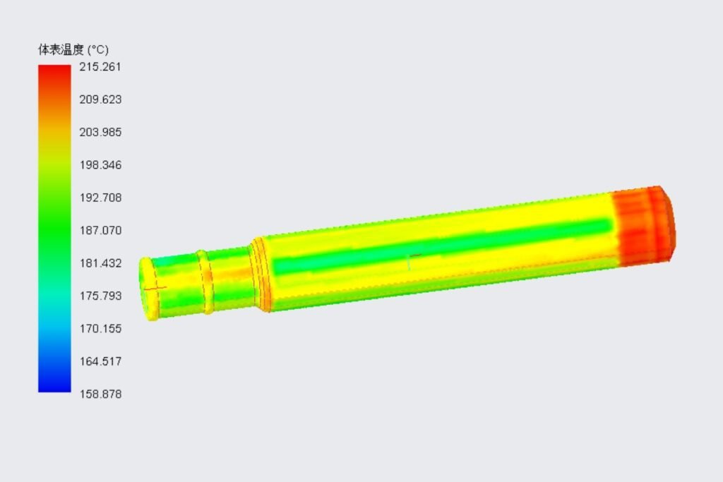
Melt Temperature Distribution
Bulk temperature gradient across the cavity remained within ±8°C at end-of-fill. Center-layer temperature (part line) stayed above minimum flow temperature throughout, confirming no hesitation in the thinnest wall regions at 1.5 mm.
Volumetric Shrinkage
Maximum volumetric shrinkage predicted at 2.8% in the pure-silicone zones — within normal range for LSR. Overmolded plastic regions showed near-zero volumetric shrinkage as expected, validating the dual shrinkage compensation strategy.
Project Outcomes
What the DFM + Mold Flow Analysis Delivered
The pre-tool engineering phase — DFM review and three rounds of simulation — resolved every risk point before steel was ordered. That sequence typically prevents 2–3 engineering change orders post-T1, each of which carries both rework cost and schedule delay on an LSR tool.
DFM risk points identified and resolved before tooling started
Gate configurations simulated before final 3×0.08 mm design selected
Target mold cycle life achieved through S136 + A50 steel selection
Press capacity used (68T actual vs 120T machine) — generous safety margin
Your Success Story Could Be Next!
Want results like these for your own production?
Reach out — let’s talk about what we can achieve together.


