

| Venting in injection molding provides an escape path for the air and volatiles displaced by advancing melt. Without adequate venting, trapped air compresses adiabatically — reaching 300°C or higher at the flow front, causing burn marks, short shots, and weld-line weakness. |
The vent depth range — 0.010 to 0.038 mm — is narrow by design: wide enough for gas to escape under injection pressure, narrow enough to freeze plastic before it flashes. Every resin has a different viscosity and therefore a different critical depth.
This article will specify vent depths by resin family, where to put those air vents in injection molding in your molds, and how to design a super effective injection molding venting system.
Why Venting Matters: The Physics of Trapped Air
When molten plastic enters a mold cavity, it must push all displaced air out through the available escape paths. The cavity has a fixed volume; the entering melt has essentially zero compressibility. Air, by contrast, is highly compressible — and that compressibility is both the problem and the physics behind the most misunderstood defect in injection molding.
Adiabatic Compression and the Diesel Effect
As melt advances, air ahead of the flow front is compressed into progressively smaller volumes at the end-of-fill locations. In a sealed cavity with no venting, the compression is adiabatic — essentially instantaneous relative to the heat transfer time scale.
Temperature rises proportional to the compression ratio: air compressed from atmospheric to 200–300 bar can reach 300–500°C, well above the ignition temperature of most polymer resins. The result is pyrolytic decomposition of the plastic at the compressed air location — the burn mark diagnostic engineers call the diesel effect. [2]
Other Failure Modes from Inadequate Venting
- Short shots occur when the pressure of compressed air equals or exceeds the injection pressure driving the melt — the melt front stalls before the cavity is full.
- Weld lines are weakened when trapped air prevents the two meeting melt fronts from achieving full molecular contact and diffusion.
- Cycle time increases because compressed gas acts as a thermal insulator, slowing heat transfer from the plastic to the mold steel and extending solidification time. [1]
Venting-Related Defects: Root Causes and Fixes
The table below maps each defect to its physical cause and the specific venting correction. Process adjustments (injection speed, pack pressure) are secondary — the primary fix for all venting-related defects is correcting the vent system design.
| Defect | What It Looks Like | Root Cause | Venting-Related Fix |
| Burn marks (diesel effect) | Blackened or scorched surface at end of fill | Trapped air compresses adiabatically, reaching 300°C+ at the flow front | Add vent at the burn location; Verify vent depth for the specific resin; Check vents are not clogged |
| Short shots | Incomplete fill — sections of the cavity missing plastic | Air pressure blocks the advancing melt front from reaching the end of fill | Add or deepen vents at last-fill locations; Verify injection speed and pack pressure |
| Weak weld lines | Visible seam; reduced tensile strength at flow-front meeting point | Trapped air at the weld prevents full molecular diffusion between the two melt fronts | Vent at weld line location; Raise melt temperature; Increase injection speed to reduce air retention time |
| Surface blemishes (flow lines, splay) | Streaks, rough patches, or flow lines on visible surfaces | Air disrupts smooth flow front advancement, causing uneven cooling and surface turbulence | Locate and vent air traps in affected flow path; Reduce injection speed in the affected zone |
| Extended cycle time | Longer fill and cooling time per cycle — increased cost per part | Compressed air acts as a thermal insulator in trapped areas, slowing heat transfer and solidification | Correct venting reduces cavity pressure and allows faster fill and shorter cooling phase |
| Mold corrosion | Rust, pitting, and premature wear on cavity surfaces | Moisture in trapped gas condenses on cooler mold steel surfaces and reacts with the metal | Vent moist-gas accumulation zones; Inspect for water contamination in resin; Improve drying protocol |
A diagnostic principle worth applying first: if burn marks appear consistently at the same location across multiple shots, the vent at that location is either absent, undersized, or clogged. If burn marks move between shots, the root cause is more likely process instability (variable injection speed or inconsistent pack pressure) rather than a static vent design flaw.
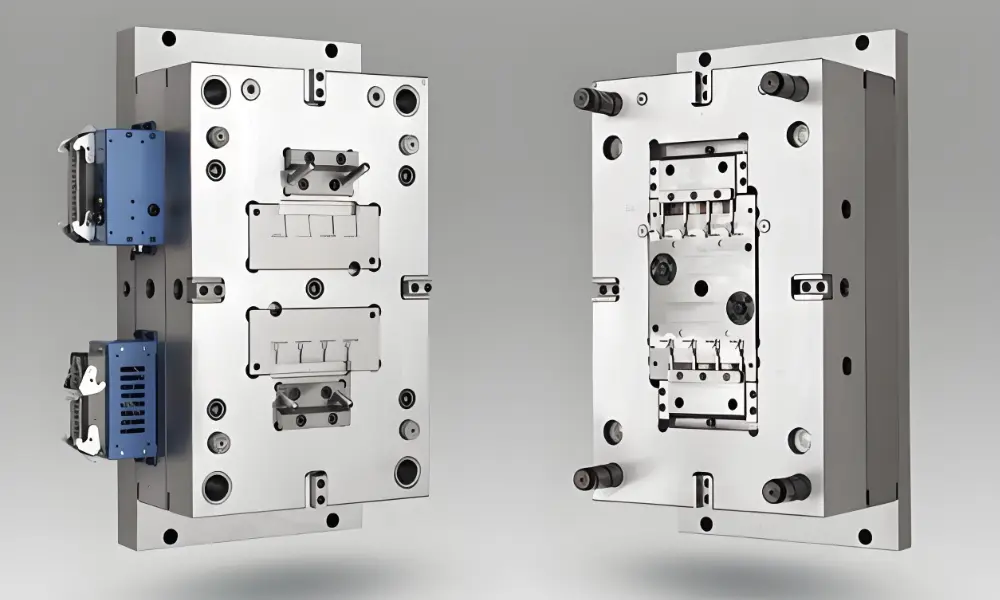
Where to Place Vents in Injection Molds: Six Primary Locations
Choosing the right spots for your vents is super important for successful venting injection molding. Here are the key areas where you should be placing them:
Parting Line
The parting line — where the two mold halves meet — is the most accessible and most commonly used vent location. Shallow channels ground into the parting face allow air to escape at the cavity perimeter as the melt advances.
Parting line vents are easy to machine and easy to clean in-machine without disassembly, making them the preferred first choice for any end-of-fill location that falls at the parting line geometry.
End-of-Fill Areas
Vents must be present at every location where the melt front arrives last. These are the points of maximum air compression — burn marks and short shots localize here when venting is absent.
Mold flow simulation predicts end-of-fill locations accurately before tooling is cut; vent positions should be specified in the simulation output, not determined empirically after first article.
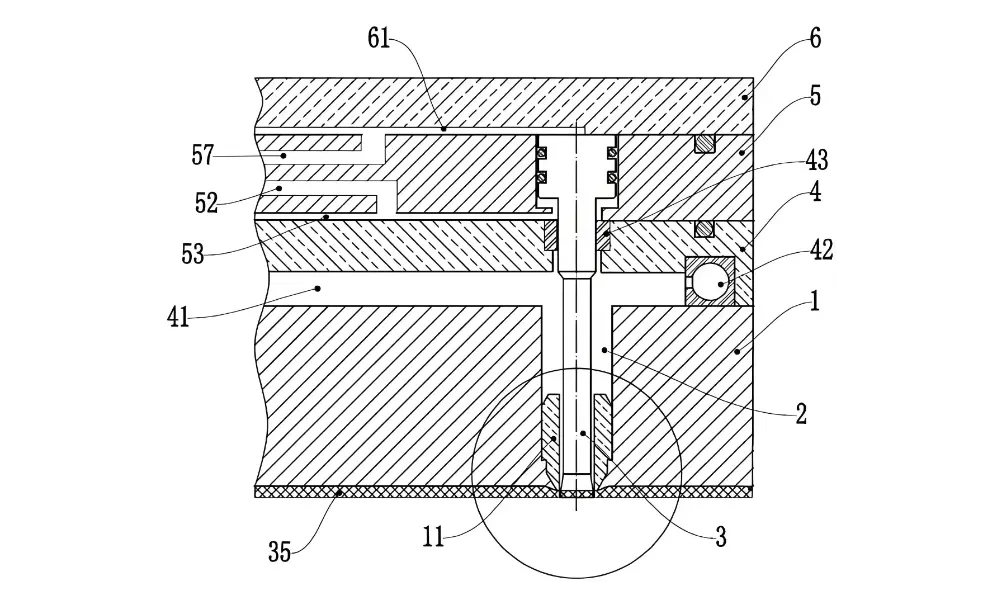
Around Ejector Pins
The clearance between ejector pin and pin bore — typically 0.005–0.015 mm — is exploited as a passive vent path. In deep ribs and blind pockets where parting line vents are not accessible, machining a small flat on the ejector pin creates a controlled vent channel.
The pin-bore clearance must be maintained within specification: too tight and it seals the vent; too loose and it allows plastic to flash and bind the pin.
Deep Ribs and Bosses
Deep ribs — walls with depth-to-width ratios above 4:1 — trap air at the root because the melt fills from the top downward and compresses the air into the closed bottom. Venting at the rib root via ejector pin channels or through-vent inserts prevents the diesel effect in these geometries.
Boss cores present the same problem: the closed end of the core creates a blind pocket that requires either a vent pin or a porous insert to evacuate.
Complex Geometries and Internal Cavities
Undercuts, hidden corners, multi-cavity sections, and internal chambers create locations where standard parting line venting cannot reach. These areas require venting through ejector pins, insert-piece vents, porous inserts, or vacuum-assist systems depending on the geometry.
Complex parts should have vent locations specified in the mold design drawing before tooling — not discovered during first-article trials.
Slides and Lifters
Slides and lifters create temporary sealed volumes when they engage — the gap between the moving insert and the cavity closes, trapping air in the undercut zone. Vent channels on the slide body or between the slide and cavity steel allow this trapped air to escape during injection.
Slide vents must retract with the slide — fixed vent geometry that becomes blocked when the slide closes defeats the purpose.
Vent Depth Specifications by Resin
Vent groove depth is the single most critical venting parameter. Too shallow: gas cannot escape fast enough, and air traps form. Too deep: plastic flashes into the vent, clogs it, and creates a parting line defect. The correct depth depends entirely on the resin’s melt viscosity at processing temperature.
| Resin Family | Vent Depth | Land Width | Engineering Notes |
| PP, PE, PS (commodity) | 0.015–0.025 mm | 3–5 mm | Best-flowing resins; slightly deeper vents acceptable without flash risk |
| ABS, PC, PC/ABS | 0.025–0.038 mm | 3–5 mm | Standard engineering resins; balance between gas escape and flash prevention |
| Nylon (PA6, PA66) | 0.013–0.020 mm | 3–5 mm | Hygroscopic — moisture generates gas; more vents often needed than depth alone suggests |
| LCP (Liquid Crystal Polymer) | 0.010–0.015 mm | 2–3 mm | Extremely low viscosity — shallowest vents in production; flash risk is high above 0.015 mm |
| PPS, PEEK (high-temp) | 0.013–0.025 mm | 3–5 mm | Processed at 300–400°C; H13 or tungsten carbide vent inserts recommended |
| TPE, TPU (flexible) | 0.025–0.038 mm | 4–6 mm | Elastic — tends to seal vents under clamp pressure; wider vents partially compensate |
Land width — the distance from the cavity edge to where the vent widens into a relief channel — controls flash risk. A land of 3–5 mm allows plastic to freeze in the vent before it passes beyond the land, even if the vent depth is at the upper limit of the range. Beyond the land, the channel can widen to 0.5–1.5 mm depth to allow easy gas escape to atmosphere.
Vent maintenance: parting line vents must be inspected and cleaned every 50,000–100,000 shots for high-temperature or fiber-filled resins. Residue buildup in the vent reduces effective depth progressively — a vent that performed correctly at first article may produce burn marks after 200,000 shots if not maintained. [1]
Eight Injection Mold Venting Methods
Here are several methods to vent in injection molds as follows:
Parting Line Vents
Ground channels on the mold parting face, typically 3–5 mm wide with a 1–3 mm land. The simplest and most common method — accessible for inspection and cleaning without mold removal from the press. Used for any end-of-fill location that falls at or near the parting line.
Vent Grooves
Wider channels ground into the parting face or sub-surface areas, used for large to medium parts where gas volume is high. Vent grooves distribute the gas flow across a longer path than a single narrow vent, reducing the tendency for plastic to flash through any one location.
Ejector Pin Vents
A flat machined on the side of an ejector pin creates a controlled vent channel within the pin bore. Effective for deep ribs, boss cores, and any internal feature where parting line venting cannot reach. The flat width is typically 0.5–1.5 mm; depth follows the same resin-specific specifications as parting line vents.
Insert Piece Venting
Separate mold inserts machined with integrated vent channels are pressed or screwed into the main mold body. This approach allows vent replacement without repairing the main cavity — worn or damaged vents are replaced as inserts rather than requiring full mold rework.
Clearance Venting
Controlled gaps between mold components — insert-to-cavity clearance, core-to-cavity clearance — serve as passive vent paths. Requires precise fit control: the clearance must be held within the vent depth specification range across the mold’s full operating temperature. Thermal expansion of mold components can change effective clearance between cold setup and hot production conditions.
Porous Insert Venting
Sintered metal inserts (typically sintered tool steel or bronze) pressed into the cavity at air trap locations allow continuous gas permeation through microscopic pores. Effective for blind pocket locations where machined vent geometry is geometrically impractical.
Porous inserts must be replaced or re-sintered periodically as pores become clogged with polymer residue, typically every 100,000–300,000 shots depending on resin.
Vacuum Venting Systems
Active vacuum systems evacuate the mold cavity to below atmospheric pressure before injection begins, eliminating the compressed air that causes the diesel effect. It’s effective for precision parts where even small gas traps are unacceptable — optical components, medical parts with tight surface specifications.
Active vacuum systems add equipment complexity and cycle time (vacuum pull-down time), but eliminates burn marks and short shots in parts where passive venting is geometrically insufficient.
Dynamic Gas Vents
Pneumatically actuated vent valves open during injection to actively assist gas expulsion and close before pack pressure is applied to prevent backflow. Used for high-cavitation tools and complex geometries where static vents cannot maintain consistent gas flow across all cavities. More complex to maintain than passive vents but provide closed-loop vent performance that can be adjusted between production runs.
Designing an Effective Venting System
Proper plastic injection mold venting will help preserve the faces of parts as trapped air and gases can escape, preventing defects and improving part aesthetics. Designing a truly effective injection molding venting system requires careful thought.
Start with Mold Flow Simulation
Mold flow simulation predicts air trap locations, end-of-fill positions, and weld line formation before any steel is cut. Vent positions specified from simulation output result in fewer first-article iterations than vents located empirically after the first trial shot.
Simulation also predicts the relative severity of air traps — which locations will generate burn marks at standard injection speed versus only at high injection speed — allowing vent priority assignment.
Specify Depth by Resin, Not by Rule of Thumb
The vent depth table above provides starting specifications by resin family. Use these as starting points for the first trial and adjust based on first-article results: burn marks at the vent location indicate the vent is too shallow; plastic flash in the vent channel indicates it is too deep.
For multi-cavity tools, verify that the vent depth specification is held to ±0.005 mm across all cavities — cavity-to-cavity vent variation is a common source of inconsistent burn marks in high-cavitation production.
Coordinate Venting and Cooling
The cooling system and vent system interact. Cooling channels that run too close to vent locations can cause the mold steel at the vent face to run cold, increasing the risk of plastic freezing in the vent and reducing effective vent cross-section over time. Maintain a minimum distance of 1.5× cooling channel diameter between any cooling circuit and a vent groove.
Plan for Maintenance Access
Every vent that cannot be cleaned in-machine will eventually be cleaned by mold disassembly — at production downtime cost. Design all parting line vents to be accessible from the parting face without mold removal. For deep-cavity vents and insert-piece vents that require disassembly, document the cleaning interval in the mold maintenance schedule and build that downtime into the production planning model.
Mold Venting at Fecision
Fecision provides injection mold design services that include venting analysis — vent location specification from Moldflow simulation output, vent depth selection by resin, and integration of venting into the cooling system layout.
- Vent design: Moldflow simulation identifies air trap locations; vent positions and depths specified in mold design drawing before tooling.
- Vent precision: vent groove depth held to ±0.003 mm via precision surface grinding; land width and relief channel dimensions per resin specification.
- Materials: H13 tool steel standard; tungsten carbide vent inserts for abrasive and high-temperature resins (GF-filled PPS, PEEK); sintered porous inserts for blind pocket locations.
- Quality: ISO 9001:2015 certified. First-article burn mark and short shot inspection. Vent maintenance intervals documented in mold maintenance schedule.
Conclusion
Venting in injection molding is a precision engineering problem, not a troubleshooting afterthought. The vent depth range — 0.010 to 0.038 mm depending on resin — is a physical constraint set by the viscosity of the material being processed, not a design preference. The six vent locations correspond to the six geometric configurations where air consistently traps; each one requires a different venting approach.
The most effective venting programs are designed from simulation output before tooling, specify vent depth by resin rather than by convention, and build maintenance access into the mold design from the start. First-article burn marks and short shots at end-of-fill locations are the diagnostic signal that the vent system design needs correction — not that the process parameters need adjustment.
Send your mold/part design to Fecision and discuss with our engineering team of your next injection molding project!
Frequently Asked Questions
What is the correct vent depth for injection molding?
Vent depth depends on resin viscosity.
- Standard ranges by family: commodity resins (PP, PE, PS): 0.015–0.025 mm;
- Engineering resins (ABS, PC): 0.025–0.038 mm;
- Nylon (PA6, PA66): 0.013–0.020 mm;
- LCP: 0.010–0.015 mm.
Depths above the upper limit for the resin cause plastic flash in the vent channel; depths below the lower limit restrict gas escape and produce burn marks.
What causes the diesel effect in injection molding?
The diesel effect occurs when trapped air ahead of the advancing melt front is compressed adiabatically to high pressure. As mold cavity pressure rises to 200–300 bar, the compressed air temperature increases to 300–500°C — sufficient to pyrolytically decompose most polymer resins at the melt front contact zone.
How many vents does an injection mold need?
No fixed rule — the number depends on part geometry, material, and fill path. As a starting point: vent at every identified end-of-fill location from mold flow simulation, every deep rib root, every boss core, and every slide/lifter interface. For multi-cavity tools, each cavity must be individually vented to equivalent depth.
How often should injection mold vents be cleaned?
- Parting line vents: inspect every 50,000–100,000 shots for standard resins; more frequently for fiber-filled and high-temperature resins that leave carbonized residue.
- Porous inserts: replace or re-sinter every 100,000–300,000 shots depending on resin.
A progressive increase in burn mark severity over production life is the diagnostic indicator that vents are partially clogged and cleaning is overdue.
When should vacuum venting be used instead of passive vents?
Vacuum venting is specified when part geometry prevents adequate passive vent coverage — typically complex 3D internal cavities, thin-wall parts where fill time is too short for passive gas evacuation, or optical/medical parts where any surface contamination from burn marks is unacceptable.
References
Accessed May 2026.
[1] Rosato, D.V. & Rosato, M.G. Injection Molding Handbook, 3rd Edition. Kluwer Academic Publishers, 2000.
[2] Menges, G., Mohren, P. & Michaeli, W. How to Make Injection Molds, 3rd Edition. Hanser Publishers, 2001.
[3] BASF SE. Ultramid Polyamide Processing Guide — Mold Design Recommendations. https://plastics-rubber.basf.com/emea/en/performance_polymers/products/ultramid


