

| Plastic enclosure design for injection molding is the engineering process of creating a hollow protective shell that can be molded at high volume while meeting dimensional, structural, electrical, and regulatory requirements. It combines material selection, wall thickness management, rib and boss geometry, draft angle specification, gate placement, and tolerance assignment — all governed by Design for Manufacturability (DFM) principles that must be resolved before a mold tool is cut. |
The most expensive mistake in enclosure development is discovering a DFM problem after the mold steel has been hardened. Changes to a hardened production tool — adding steel to reduce a wall, re-machining a gate location, adjusting an ejector pin position — can result in unnecessary expenses per modification and delay production per iteration.
The eleven rules below address the decisions that most frequently cause late-stage tool rework. None of them are complex in isolation — but they interact, and failing to consider them together is what drives post-steel rework costs.
What Is Injection-Molded Enclosure Design?
An injection-molded enclosure is a hollow plastic shell designed to house, protect, and interface with electronic or mechanical components. The enclosure must simultaneously satisfy the structural and thermal demands of its service environment, the electrical safety requirements of its market (UL 94 flammability, EMC, IP rating), and the geometric constraints of the injection molding process.
The molding process constraint is not an afterthought. Every surface, edge, and internal feature must be designed to fill completely, cool uniformly, and release from the mold tool without damage — at high volume, cycle after cycle, with part-to-part dimensional variation within the specified tolerance. A design that is functionally perfect but geometrically unmoulable requires expensive tool rework or design changes before production can begin.
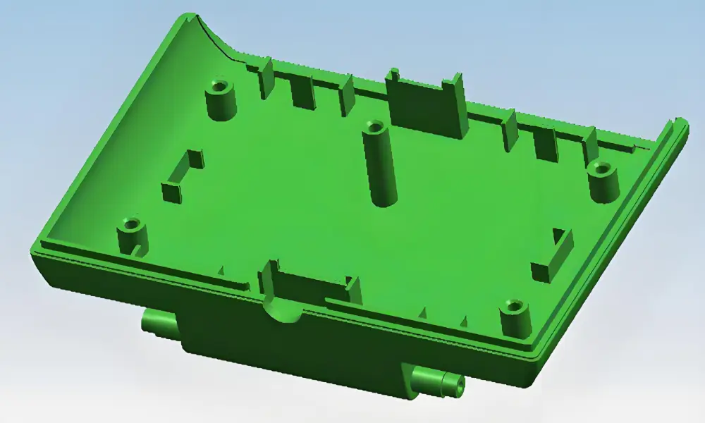
The Three Elements of a Successful Enclosure Design
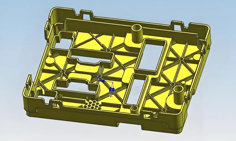
Mold geometry (cavity and core): The 3D surfaces that define the enclosure’s external appearance, internal pocket geometry, and all functional features. Every surface must have adequate draft to release cleanly.
Wall architecture: The wall thickness profile, rib layout, and boss configuration that determine structural performance, cooling time, sink mark risk, and warpage tendency.
Assembly and interface features: Snap fits, living hinges, boss locations for self-tapping screws, alignment pins, and gasketing lands — all molded in a single shot without secondary operations.
Material Selection for Injection-Molded Enclosures
Material selection is the first and most consequential decision in enclosure DFM. The chosen resin determines wall thickness requirements, minimum draft angles, achievable tolerances, surface finish options, and which regulatory certifications the enclosure can realistically obtain.
Amorphous resins (ABS, PC, PS) shrink 0.4–0.7% and provide tighter dimensional tolerances with lower warpage risk. Semi-crystalline resins (PP, PA, HDPE) shrink 1.0–3.5% and require more careful warpage analysis but offer better chemical resistance and fatigue performance for living hinges and snap features. [1]
| Material | Rec. Wall | Min Draft | Shrinkage | Engineering Notes for Enclosure Design |
| ABS | 1.5–3.0 mm | 2° | 0.4–0.7% | The default enclosure resin. Good impact resistance, easy to paint and texture, low cost. Poor UV stability without additives — outdoor enclosures need UV-stabilised grade or a painted/coated exterior. |
| Polycarbonate (PC) | 2.0–3.5 mm | 2°–3° | 0.5–0.7% | Superior impact resistance and optical clarity. Required for transparent covers and windows. Higher melt temperature — gates must be larger to prevent premature freeze-off. Sensitive to sharp corner stress cracking. |
| ABS+PC Blend | 1.8–3.0 mm | 2° | 0.5–0.8% | Balances PC’s impact strength with ABS’s processability and surface quality. The standard choice for mid-range electronic enclosures balancing performance and cost. |
| Polypropylene (PP) | 1.0–3.0 mm | 1°–2° | 1.0–2.5% | Lightest structural enclosure resin. Chemical resistance, living hinge capability (excellent at 0.3 mm), low cost. Higher shrinkage — more critical to simulate warpage before committing to tooling. |
| Nylon (PA66) GF-30 | 2.0–3.5 mm | 1°–1.5° | 0.3–0.8% | 30% glass-filled nylon for enclosures requiring stiffness in elevated temperatures (hood-mounted electronics, industrial controls). Hygroscopic — pre-dry to <0.2% moisture before molding. |
| HDPE | 1.5–3.0 mm | 1°–2° | 1.5–3.5% | Chemical resistance and low-temperature impact performance. Used in outdoor utility enclosures and harsh-environment junction boxes. High shrinkage requires careful flow analysis. |
A practical note on glass filling: Adding 10–30% glass fibre to nylon or PC reduces shrinkage and increases stiffness, but introduces anisotropic (directional) shrinkage — the part shrinks differently parallel and perpendicular to the flow direction. This anisotropy must be accounted for in mold flow simulation before tooling is cut; otherwise, enclosure halves will not align correctly at assembly.
11 DFM Rules for Plastic Enclosure Design
The following rules address the decisions most commonly responsible for tool rework, production defects, and tolerance failures in enclosure programs. Each rule includes the engineering rationale — not just the specification.
1. Wall Thickness — Uniform, Within the Recommended Band
For amorphous resins (ABS, PC, ABS+PC), hold walls between 1.5 and 3.0 mm. Polypropylene can go thinner — to 1.0 mm for living hinges — and structural PC should be at the upper end (2.5–3.5 mm) for impact-critical enclosures.
Uniform thickness is more critical than the absolute value. When a thin wall transitions abruptly to a thick section, the thick section cools more slowly, pulling material from the adjacent thin wall during solidification. The result is a sink mark on the cosmetic face — typically visible on the outer surface directly opposite the thick section.
Transition any thickness change with a taper or chamfer over a distance of at least 3× the thickness differential. This distributes the differential cooling gradually and keeps sink marks below the threshold of visibility for most surface finish grades.
→ Internal: Avoiding sink marks in injection molding
2. Rib Geometry — Stiffness Without Sink
Target rib width at 50–60% of the adjacent nominal wall thickness. A rib that is too wide acts like a thick wall section and produces the same sink mark problem. Height should be limited to 3× the wall thickness; taller ribs trap air and produce incomplete fill (short shots) at the rib tip even at full cavity pressure.
The base of every rib needs a radius — minimum 0.25 mm, preferred 0.5 mm. A sharp rib root concentrates stress under flexural loading and creates a notch that initiates cracking under drop impact. The radius also reduces the local stress during ejection, when the part is still warm and the rib must flex slightly to release from the mould surface.
3. Boss Design — Secure Screw Attachment Without Pull-Out
Boss outer diameter should be at least 2× the screw outer diameter. For M3 self-tapping screws (3 mm OD), a 6 mm boss outer diameter is the minimum — 7 mm is preferred for repeated assembly cycles. Thinner bosses crack radially on the first assembly cycle when screw insertion stress exceeds the plastic’s tensile yield.
Add triangular gussets from the boss base to the adjacent wall or floor — two gussets at 90° to each other is standard. Gussets transfer the torque load from the boss into the enclosure wall rather than relying on the boss root alone. Boss height should not exceed 2.5× the boss outer diameter; tall unsupported bosses deflect visibly under moderate screw torque.
4. Draft Angles — Matched to Surface Texture Depth
For smooth, unpainted cosmetic surfaces: 1°–2° minimum per side for ABS and PC. For lightly textured surfaces (VDI 18–24, bead-blast equivalent): 2°–3° minimum. For medium-depth texture (VDI 27–30, typical enclosure grain): 3°–5°. For deep texture (VDI 33–36, leather grain): 5°–8° or more.
The industry formula for textured surfaces: add 1° of draft for every 0.025 mm of texture depth. Texture depth is measured from the peak of the texture to the trough. A VDI-30 texture has approximately 0.45 mm depth — requiring a minimum of 3° additional draft beyond the base structural draft.
Insufficient draft on a textured surface produces ‘drag marks’ — linear scratches in the texture that appear during ejection as the part surface abrades against the mould texture under friction. These are extremely difficult to hide and require mould texture stripping and re-etching to correct.
→ Internal: Draft angle in mold design — complete guide
5. Corner Radii — Stress Distribution and Flow
Sharp internal corners are the leading cause of stress-concentration cracking in injection-moulded enclosures under drop or impact loading. The plastic at a sharp corner cools faster than the surrounding material, creating residual stress — then the corner acts as a notch to initiate crack propagation under any subsequent load.
Target internal corner radius at 50–75% of the nominal wall thickness. For a 2.5 mm wall, an internal radius of 1.25–1.9 mm is appropriate. The external radius should equal the internal radius plus the wall thickness, maintaining uniform wall section around the corner.
Corner radii also improve mold filling. Plastic flows around a radiused corner more smoothly than a sharp corner — reducing the hesitation mark (a visible surface blemish) that can form where flow momentarily slows at a sharp internal corner.
6. Gate Location and Flow Pattern
Gate placement controls where the weld line forms. A weld line is the seam where two plastic flow fronts meet after flowing around a core pin or obstruction. Weld lines are weaker than the surrounding material — typically 30–60% lower tensile strength in the weld direction — and are visible on transparent or glossy surfaces.
For enclosures, keep weld lines away from: snap-fit cantilever roots (highest stress location on the snap), living hinge axes, boss bases, and any window or lens opening where the weld line would be visible. Mold flow simulation (Moldex3D, Moldflow) confirms weld line locations before tooling is cut. [2]
Gate type matters for cosmetic enclosures. Submarine (tunnel) gates on ribs or bezel flanges allow automatic gate vestige removal during ejection and keep vestige marks hidden from cosmetic faces. Fan gates on non-cosmetic interior walls deliver low injection velocity at the gate, reducing jetting and surface blemishes. Direct sprue gates on enclosure interiors are the simplest but leave a visible witness mark.
→ Internal: Injection molding gate types — complete list
7. Parting Line Placement — Flash Control and Sealing
The parting line determines where flash can form and where it cannot. Flash — the thin fin of plastic that forms at any gap between mold surfaces — is acceptable in locations where it can be trimmed or hidden. It is not acceptable on IP-rated gasketing seats, optical surfaces, or O-ring grooves, where even 0.05 mm of flash prevents proper sealing.
For IP-rated enclosures, run the parting line along a gasket land or grip ridge — a raised surface feature that concentrates the sealing contact away from the parting line edge. The gasket land must be flat to within 0.05 mm across its full perimeter; any step at the parting line will create a leak path under IP test conditions.
Flash is minimized by tight mold shutoff (typically < 0.03 mm gap), adequate clamp force, and controlled injection pressure. If a cosmetically perfect parting line surface is required, specify it on the drawing — it drives tooling cost but is achievable with hardened steel and precise EDM finishing.
8. Snap Fits and Living Hinges — Designed for Cyclic Loading
Cantilever snap fits: The critical design parameter is strain at maximum deflection — not force. ABS tolerates approximately 2% strain at the snap root before yielding. PC tolerates 3–4%. PP tolerates 6–8%, making it the best choice for high-cycle snap applications.
Strain formula for a cantilever snap: ε = (1.5 × δ × t) / L², where δ is deflection, t is root thickness, and L is snap arm length. Keep ε below the material’s permissible strain level and add a generous root radius (minimum 0.5 mm) to prevent notch-induced fracture on the first assembly cycle.
Living hinges in polypropylene: Target thickness between 0.25 and 0.35 mm. Thinner than 0.25 mm is difficult to fill consistently; thicker than 0.35 mm creates a fold crease rather than a true hinge bend. The hinge must be flexed 5–10 times immediately after molding, while the PP is still warm, to orient the molecular chains along the hinge axis — this is what gives PP living hinges their exceptional fatigue life of millions of cycles.
9. Venting and Ejection — Prevention of Burn Marks and Distortion
Vents allow trapped air to escape as plastic fills the mold cavity. Trapped air compresses under injection pressure, heats adiabatically, and burns the plastic — producing the black burn marks that appear at the end of fill. Vent depth must be shallow enough to prevent flash: 0.01–0.02 mm for ABS and PC, 0.02–0.03 mm for PP, with a vent land of 1.0–1.5 mm before the exit channel.
Place vents at every end-of-fill location: rib tips, boss tops, and any blind feature that traps air. Vents at the parting line can be machined as shallow channels; vents at ejector pins are standard practice, using the clearance between the pin and the bore as the escape path.
Ejection pad design: Add small flat pads on rib surfaces to give ejector pins a pushing surface. Ejector pins bearing directly on a cosmetic outer wall leave witness marks — particularly on glossy or plated surfaces. Locating ejector contact on internal structural features keeps the part undistorted and the cosmetic surface clean.
10. EMI/ESD Integration — Functional Protection Molded In
Plastic enclosures can achieve electromagnetic shielding through three routes: conductive compounding, post-mold coating, and molded-in contact features. The right approach depends on the required attenuation level and production volume.
Conductive compounding (carbon black or stainless fiber in ABS or PC): achieves 20–40 dB shielding effectiveness — adequate for many Class B EMC applications. The resin is injection-molded normally; no secondary operation is needed. The trade-off is surface resistivity in the 10²–10⁴ Ω/sq range, which produces a slightly textured, non-paintable surface.
Post-mold conductive coatings (copper or nickel sputter, conductive paint): achieve 40–80 dB attenuation — appropriate for Class A EMC or military specifications. Requires secondary handling operations and adds $0.50–$3.00 per enclosure half. The mulded enclosure must be designed with uniform wall thickness to prevent shadow areas during coating.
Ground bosses: For ESD protection, boss features that contact the PCB ground plane when the enclosure is assembled provide a direct path to chassis ground. Position these bosses to mate with dedicated PCB ground pads per IPC-2221B clearance requirements. [3]
11. Tolerances — Specify Only Where They Are Needed
Applying tight tolerances globally to an injection-molded enclosure drawing increases tooling cost 30–60% and often cannot be achieved on large flat surfaces regardless of investment. The correct approach is to apply the minimum tolerance tier to each feature class.
| Tolerance Tier | Typical Range | Typical Application in Enclosures | Tooling and Process Implication |
| Commercial (standard) | ±0.25 mm | General enclosure dimensions, overall length/width/height, fastener locations not mating with metal | Default tier — achievable in standard multi-cavity tooling without additional process control measures |
| Fine (precision) | ±0.10 mm | PCB pocket dimensions, connector cutout width, hinge pin bore diameter | Requires single-cavity or validated 2-cavity tooling, CpK monitoring on critical features |
| Close (high precision) | ±0.05 mm or tighter | Lens seat diameter, EMI gasketing groove width, mating snap geometry | Requires tight-tolerance mold steel (±0.005 mm EDM), validated process, CpK ≥ 1.67 on critical dimensions |
| Note on tolerance zones | — | Apply close/fine tolerances only to the specific features that require them | Applying tight tolerances globally inflates tooling cost 30–60% without quality benefit on non-critical features |
The most common tolerance mistake is specifying ±0.05 mm on overall enclosure length. Enclosures 200 mm long experience differential thermal shrinkage from edge to center during cooling. Achieving ±0.05 mm on a 200 mm dimension requires validated process control with statistical verification — not just a tighter mold. Specify ±0.05 mm for the PCB pocket width (where it matters for board fit) and ±0.25 mm for overall enclosure length (where it has no functional consequence).
Bonus: Prototype Before Committing to Production Steel
SLA or SLS prints at 0.1 mm layer resolution are adequate for checking snap-fit geometry, boss alignment, and assembly clearances. Soft (aluminium) tooling for small enclosures (<150 mm) can produce 50–200 injection-molded prototypes in the production resin for $3,000–$8,000 — enough to validate snap force, surface finish, and dimensional accuracy before $30,000+ of hardened production steel is committed.
Measure snap deflection force on prototypes against the predicted value from the strain calculation. If the measured force differs by more than 20%, recalculate with the actual material modulus from the supplier’s datasheet — nominal modulus values in material databases often differ from the actual compound used.
The Role of Mold Flow Simulation in Enclosure DFM
Mold flow simulation (Moldex3D, Autodesk Moldflow) should be run on every new enclosure program before tooling is ordered. The simulation predicts: fill pattern and weld line locations, sink mark risk from wall thickness variation, warpage tendency from differential shrinkage, injection pressure and clamp force requirements, and gate freeze time affecting packing pressure efficiency.
Every gate location and runner layout in this guide can be confirmed or corrected through simulation before a millimeter of steel is machined.
IP Ratings and What They Require of Your Enclosure Design
IP (Ingress Protection) ratings per IEC 60529 are determined by two digits: the first defines solid particle protection, the second defines liquid ingress protection. IP54 is the most common target for handheld equipment; IP65 and IP67 are standard for portable outdoor and industrial equipment.
| IP Rating | Solid | Liquid | Design Implications for the Injection-Moulded Enclosure |
| IP54 | Dust protected | Splashing water | Gasket groove required at parting line. Gasket land flatness to ±0.1 mm. No sharp parting line flash permitted. Tolerance control on groove width for O-ring compression. |
| IP65 | Dust tight | Low-pressure water jets | As IP54, plus: all cable entry glands must be sealed, no unsealed vent openings in the housing. Enclosure wall must sustain test water pressure without deflecting enough to break the gasket seal. |
| IP67 | Dust tight | Temporary immersion (1 m, 30 min) | As IP65, plus: O-ring groove dimensions must hold ±0.05 mm for consistent compression ratio. Parting line shutoff to < 0.03 mm gap. All PCB pockets must drain inward, not toward the gasket plane. |
Enclosure Design and Production at Fecision
Fecision’s DFM review process addresses all eleven design rules above before tooling is approved. Our engineering team reviews submitted CAD for wall thickness uniformity, draft angles against specified texture, rib and boss geometry, gate and parting line placement, and tolerance tier appropriatenes.
- Tooling precision: Slow-wire EDM to ±0.005 mm on critical mould features. S136 stainless steel for optical surface and IP-rated sealing features.
- Surface finishes: SPI A-1 through D-3, VDI 12–45 texture, laser texture, pad printing, and EMI conductive coating — all available as integrated services.
- Material capability: ABS, PC, ABS+PC blend, PP, PA66-GF30, HDPE, TPU, and engineering resins. Conductive-filled grades for EMI applications.
- Quality: ISO 9001:2015 certified. CMM inspection on critical enclosure features with CpK monitoring. Dimensional reports included with first-article samples.
Fecision excels in injection molded enclosure production by focusing on the tight tolerances critical for housing complex electronics. Our ISO-certified processes ensure the dimensional stability of critical features like snap-fits and bosses.
Ready to discuss your challenges? Submit CAD for a DFM review at fecision.com/contact-us.
Frequently Asked Questions
What wall thickness should I use for an ABS injection-moulded enclosure?
For ABS, the recommended wall thickness band is 1.5–3.0 mm.
- Walls thinner than 1.5 mm are difficult to fill consistently at the injection pressures used for general production tooling and may produce incomplete fill in corners and boss areas.
- Walls thicker than 3.0 mm create extended cooling times, sink risk on cosmetic faces, and higher material cost per part.
- The most important requirement is uniformity — abrupt thickness transitions cause differential shrinkage that produces sink marks and warpage, regardless of absolute wall value.
What is a weld line and why does it matter for enclosures?
A weld line (also called a knit line) forms where two plastic flow fronts meet after separating around a core pin, hole, or obstruction. In enclosures, weld lines matter most at snap-fit cantilever roots (high stress under deflection), living hinge axes, and any transparent window or lens where the weld line is visible as a faint seam.
How do I achieve IP65 or IP67 on an injection-molded enclosure?
IP65 and IP67 both require dust-tight construction (first digit 6) and liquid sealing (second digit 5 = water jets, 6 = temporary immersion).
IP testing per IEC 60529 must be performed on physical enclosure samples — mould simulation cannot replace physical test certification.
References & Authoritative Sources
Accessed April 2026.
[1] SPI: The Plastics Industry Association / ASME B4.1. Injection Molding Tolerances and Shrinkage Data. https://www.plasticsindustry.org/
[2] Protolabs Design Guide — Injection Moulding. https://www.protolabs.com/resources/design-tips/injection-molding-design-guide/
[3] IPC-2221B: Generic Standard on Printed Board Design. https://www.ipc.org/


