

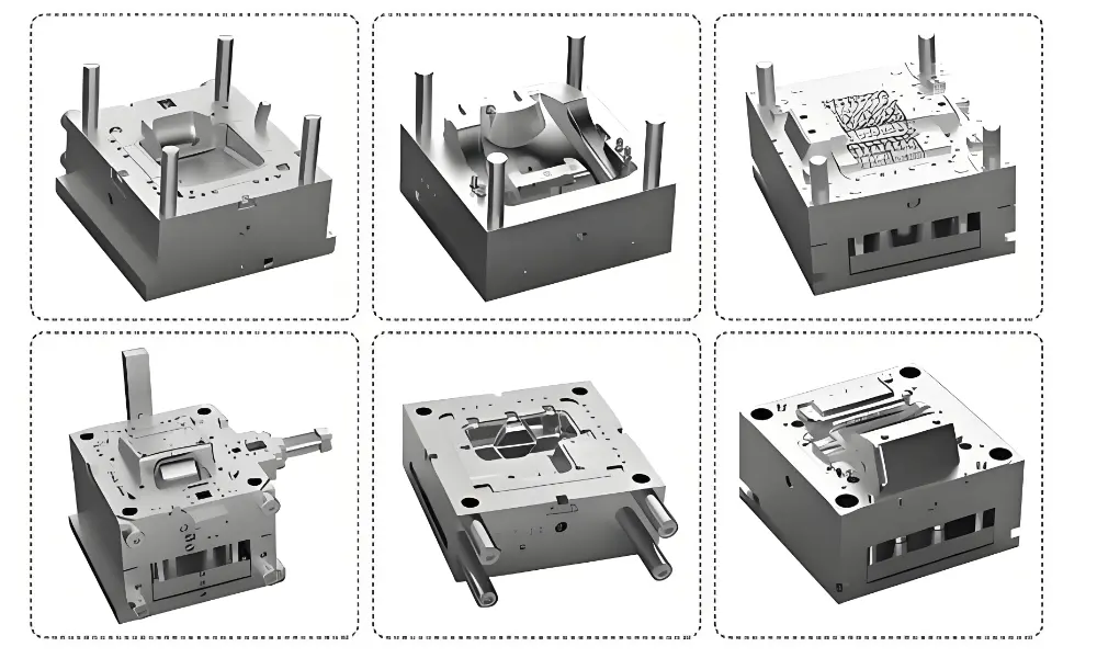
| An injection mold contains over 20 components organised into seven functional systems: the mold base (structure), cavity and core (part shaping), feed system (melt delivery), cooling system (temperature control), ejection system (part removal), venting system (gas evacuation), and guidance system (alignment). Each must work together to maintain ±0.05mm dimensional tolerances through thousands of production cycles. |
An injection mold looks like a solid steel block from the outside. Inside, it is a precision system where every component has a defined function — and a failure in any one of them shows up directly in the molded part.
This guide covers all major injection mold components: what they do, what they are made of, how they are specified, and — critically — which component is responsible when a defect appears.
Quick Reference — All Injection Mold Components
| Component | Function | Typical Material | Key Specification |
| Mold Base | Structural framework | S50C / 1050 steel | Houses all inserts and systems; must resist clamping deflection |
| Cavity (A-side) | Forms external part surfaces | H13, S136, NAK80 | Finish from SPI A-1 mirror to D-3 sandblast depending on part aesthetics |
| Core (B-side) | Creates internal features | H13, S136, P20 | Typically on moving side; integrates cooling baffles for deep sections |
| Sprue Bushing | Machine nozzle interface | H13 HRC 52–54 | 2–4° tapered channel; radius matched to machine nozzle (3.5–4.0mm) |
| Runners & Gates | Melt delivery to cavity | Same steel as base | Gate thickness: 50–80% of part wall to prevent shear heating |
| Cooling Channels | Temperature control | Mold steel / BeCu | Accounts for 60–70% of total cycle time; turbulent flow preferred |
| Ejector Pins | Part removal | SKH51 HRC 60–62 | H7/f7 clearance fit; balanced distribution prevents part distortion |
| Guide Pins/Bushings | Mold half alignment | SUJ2 HRC 60–62 | H7/g6 fit; must engage 1.5× diameter before cavity contacts core |
| Vents | Air and gas evacuation | Parting line steel | 0.02–0.05mm depth; insufficient venting causes burn marks and short shots |
| Sliders | External undercut features | H13 + locking heels | Angle pins 15–20°; travel = 1.5× undercut depth minimum |
| Lifters | Internal undercut features | H13 or tool steel | 5–10° angle; limited to ~15mm undercut travel |
| Hot Runner System | Waste-free melt delivery | Manifold + nozzles | PID control ±1°C per zone; ROI justified above ~50,000 shots |
Types of Injection Molds
Before understanding injection molds and their basic types, what is injection molding?
Injection molding is a manufacturing process used to produce large quantities of plastic parts. It works by melting plastic pellets, injecting the liquid plastic into a mold, and cooling it to form a solid shape. This method is fast, efficient, and great for making strong, lightweight, and detailed parts.
Mold type determines how many parts are produced per cycle, how complex the tooling is, and what it costs to build and maintain. The table below summarises the eight main types. [1]
Single-Cavity Mold
The simplest type — produces one part per injection cycle.
- Advantages: Low cost, fast to build and modify, excellent quality control, low defect risk. Ideal for prototyping, design verification, or low-to-medium volume production.
- Limitations: Low output; not efficient for high volumes (switch to multi-cavity needed for scale).
Multi-Cavity Mold
Produces multiple identical parts in one cycle (e.g., 4, 8, 16, or 64+ cavities, depending on part size and machine).
- Advantages: Dramatically increases production speed, lowers cost per part, perfect for high-volume runs.
- Limitations: More complex and expensive to design/build; requires precise balancing of runners, cooling, and venting to ensure uniform filling and quality across all cavities.
Family Mold
A multi-cavity mold that produces multiple different but related parts (e.g., left/right mirror housings or a set of fasteners) in one cycle.
- Advantages: Saves cost vs. separate molds for each part; good for medium-volume production of part families.
- Limitations: Harder to balance flow/cooling due to varying geometries; higher risk of defects or inconsistent shrinkage.
Two-Plate Mold
The most common and basic design — uses two plates (fixed A-side with cavity, moving B-side with core). Gate and runners eject with the part.
- Advantages: Simple structure, low cost, easy to maintain and operate. Suitable for most standard parts.
- Limitations: Runners/gates require trimming; less ideal for high-aesthetic needs.
Three-Plate Mold
Adds a third (runner) plate between fixed and moving sides for separate runner ejection.
- Advantages: Clean gate marks, automatic runner separation (no manual trimming needed). Great for parts with strict cosmetic or aesthetic requirements.
- Limitations: More complex and expensive than two-plate molds.
Two-Shot / Multi-Shot Mold
Allows sequential injection of two (or more) different materials/colors in the same mold (e.g., rigid base + soft grip, or multi-color parts). Uses rotating cores or transfer methods.
- Advantages: Eliminates assembly steps, stronger bonding, premium look/feel. Popular for automotive interiors, consumer goods, tools.
- Limitations: Requires specialized equipment and precise design; higher tooling cost and complexity.
Insert Mold
Pre-formed inserts (usually metal — pins, terminals, bushings, threads) are placed in the mold, then plastic is injected around them.
- Advantages: Creates strong hybrid parts without separate assembly; widely used in electronics, automotive sensors, medical handles.
- Limitations: Needs accurate insert positioning, heat control, and flash prevention.
Stack Mold
Stacks multiple parting lines/cavities vertically, fed from one injection point — effectively doubles (or more) output without larger machine tonnage.
- Advantages: High output for flat/thin-walled parts (e.g., lids, trays, containers); maximizes efficiency in high-volume production.
- Limitations: Very expensive, mechanically complex, requires precise synchronization and balancing.
For most new programs, two-plate or three-plate molds are the starting point. Multi-cavity and stack molds make sense once volumes justify the higher tooling investment. Two-shot and insert molds require specialised machines and careful design coordination.
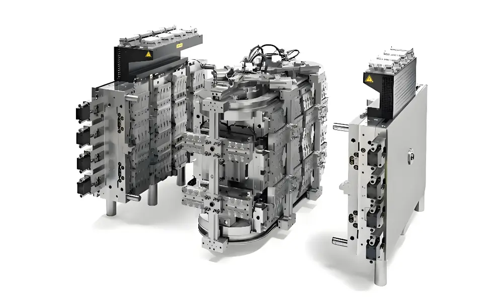
Mold Base and Structural Components
The mold base is the steel framework that holds every other component in precise alignment. It must withstand clamping forces of 50–3,000 tons without deflecting enough to cause parting line separation.
Most mold bases use S50C carbon steel — strong, machinable, and available in standard sizes. The base consists of several sub-plates, each with a specific structural role.
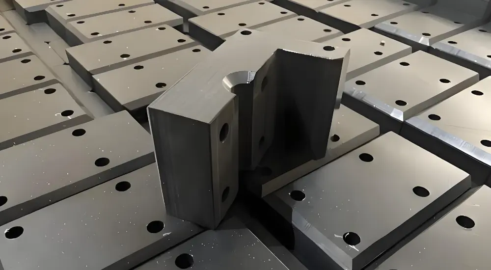
Standard Mold Base Plates
- A Plate (Cavity Plate): Stationary side. Houses the cavity insert. Made from S50C; hardness 200–230 HBN.
- B Plate (Core Plate): Moving side. Houses the core insert and typically integrates ejector system access.
- Support Plate: Prevents B plate deflection under injection pressure. Thickness calculated per unsupported span.
- Ejector Housing (Spacer Blocks): Creates the stroke space for the ejector plate to travel during part removal.
- Ejector Retainer and Backing Plates: Hold ejector pins in position; distribute force from machine ejector rods.
- Clamping Plates (Top / Bottom): Interface directly with machine platens. Locating ring fits here.
Support pillars are placed between the B plate and ejector backing plate to prevent deflection under cavity pressure. A general rule: one pillar per 100–150cm² of projected part area in high-pressure zones. Standard diameter is 25–40mm depending on mold size.
Cavity and Core: The Part-Shaping System
The cavity and core are the two components that actually define the shape of the finished part. Everything else in the mold exists to support their function.
The cavity (A-side, stationary) forms external surfaces, textures, and visible features. The core (B-side, moving) creates internal geometry — holes, bosses, ribs, and channels.
Cavity Specifications
- Location: Stationary platen — the side the machine nozzle touches.
- Surface finish: SPI A-1 (mirror polish, Ra ≤0.012µm) for optical parts down to D-3 (sandblast, Ra ~6µm) for texture. [2]
- Draft angle: 0.5°–3° per side; deeper texture requires more draft (typically 1° per 0.025mm texture depth).
- Hardness: HRC 48–52 for hardened grades; pre-hardened P20 at HRC 28–32 for prototype work.
Core Specifications
- Location: Moving platen — travels with mold opening and integrates the ejector system.
- Clearance fit with cavity: 0.01–0.03mm to prevent flash while allowing thermal expansion.
- Cooling integration: Deep cores use baffles or bubblers — a central supply tube with annular return — to reach cooling fluid into the tip.
Cavity / Core Steel Selection
Steel grade is the most consequential single decision in mold design. The wrong choice shows up in the first 50,000 shots as premature wear or dimensional drift.
| Steel Grade | Hardness | Tool Life | Best For | Key Note |
| P20 | HRC 28–32 | <100k shots | Prototyping, low volume, non-abrasive resins | Baseline cost; available pre-hardened, no post-machining heat treat needed |
| H13 | HRC 48–52 | 500k–1M+ shots | High-volume, glass-filled resins (GF30+), hot work | Minimum grade for glass-filled materials; GF30 erodes P20 within 50k shots |
| S136 | HRC 48–52 | 400k–800k shots | Medical, PVC, corrosive materials | Stainless; corrosion resistance essential where moisture or PVC contact exists |
| NAK80 | HRC 38–42 | 200k–500k shots | High-gloss cosmetic parts, optical housings | Pre-hardened; excellent polishability without full heat treatment |
| BeCu (inserts) | HRC 30–38 | 300k–600k shots | High-heat zones, rapid local cooling | 4× thermal conductivity of steel; used where standard cooling cannot reach |
Selection note: Glass-filled resins (GF15, GF30) require H13 minimum. P20 erodes within 50,000 shots under abrasive fill. For PVC or medical applications, S136 stainless is mandatory for corrosion resistance.
At Fecision, S136 cavities are machined to ±0.002mm using slow-wire EDM machines. DLC (Diamond-Like Carbon) coating at ≥2,200 HV is applied to high-wear surfaces for medical and long-run programs.
Feed System: Sprue, Runners, and Gates
The feed system is the plastic’s path from machine nozzle to mold cavity. Its job is to deliver melt at the right temperature and pressure with as little waste and degradation as possible.
Sprue Bushing
The sprue bushing connects directly to the machine nozzle. Its radius must match the nozzle radius closely — a mismatch of even 0.5mm causes leak-back and drooling.
Standard taper: 2–4° included angle to allow sprue removal on ejection. Material: H13 hardened to HRC 52–54 to withstand the repeated thermal cycling and mechanical contact with the machine nozzle.
Runner System
- Cold runner: Runner solidifies each cycle and ejects with the part. Diameter 3–8mm. Waste is 15–30% of shot weight (can be reground).
- Hot runner: Heated manifold keeps melt molten between cycles. Near-zero waste. PID temperature control ±1°C per zone. Generally, ROI justified at volumes above ~50,000 shots.
Gate Design
The gate is where melt enters the cavity. Its size and location affect fill uniformity, cosmetic appearance, cycle time, and packing pressure.
Critical rule: gate thickness should be 50–80% of part wall thickness. Too thin causes shear heating and material degradation; too thick freezes late and prevents pack-out.
| Gate Type | Dimensions | Application | Advantage | Limitation |
| Edge Gate | 0.8–2.0mm thick, 2–4mm wide | General purpose parts | Simple, low-cost | Requires manual trimming; visible gate mark on edge |
| Submarine (Tunnel) | 0.5–1.2mm dia. | Auto-degating applications | Self-shearing on ejection | Gate mark on non-cosmetic surface; limited to flexible resins |
| Pin Point | 0.8–1.5mm dia. | Cosmetic/optical surfaces | Minimal gate vestige | Three-plate mold required; higher tooling cost |
| Fan Gate | 0.5–1.5mm thick, wide | Flat or large parts | Reduces flow stress | Wide gate improves fill uniformity; trim line visible |
| Hot Tip | 0.8–2.0mm orifice | Hot runner systems | No runner waste | Requires accurate temperature control; higher system cost |
Cooling System: Temperature Control
Cooling accounts for 60–70% of total injection cycle time. That number surprises most first-time tool designers. Optimising the cooling system is where cycle time improvements come from — not from faster injection.
The goal is uniform temperature across the cavity surface — typically within ±5°C — to achieve consistent shrinkage and prevent warpage, sink marks, and internal stress.
Cooling Channel Parameters
- Channel diameter: 8–12mm standard; 6mm for small molds. Balances coolant flow rate against local mold strength.
- Pitch distance: 2.5–3.5× channel diameter (20–40mm typical). Too close weakens the steel; too far apart creates hot spots.
- Distance from cavity surface: 1.5–2.0× channel diameter (12–24mm). Closer improves efficiency; too close risks deflection under injection pressure.
- Coolant velocity: Target turbulent flow above 0.8 m/s. Turbulent flow improves heat transfer by approximately 40% compared to laminar flow.
Advanced Cooling Strategies
- Baffles and bubblers: Used for deep cores where standard drilling cannot reach. A central tube delivers coolant to the tip; the annular space returns it. Essential for cores deeper than 100mm.
- Conformal cooling: Channels 3D-printed (DMLS) or vacuum-brazed to follow cavity geometry. Reduces cooling time 20–40% for complex parts with non-uniform wall thickness.
- Differential temperature strategy: Cavity side typically held 10°C higher than core side. This causes plastic to shrink onto the core — making ejection easier without sticking.
Ejection System: Part Removal
After cooling, the ejection system pushes the part off the core. It sounds simple. In practice, it is one of the most common sources of part defects, particularly surface marks, distortion, and dimensional variation near ejection locations.
Ejector Pins
The most common ejection element. Flat-head pins leave a small witness mark (0.1–0.3mm) on the part surface — acceptable on non-cosmetic areas.
- Standard diameters: 1.5mm, 2.0mm, 2.5mm, 3.0mm, 4.0mm, 5.0mm, 6.0mm. Select based on ejection force required and available surface area.
- Material: SKH51 high-speed steel, hardened to HRC 60–62. Must be harder than the surrounding mold steel to resist galling.
- Clearance fit: H7/f7 — a precision sliding fit that prevents binding while keeping flash to a minimum.
- Ejection force: 0.5–1.0 ton per pin. Balanced distribution is critical — uneven force across the part causes warpage and dimensional error.
Ejector Sleeves
Used for cylindrical bosses or through-holes. A sleeve provides 360° uniform ejection force around the feature — preventing the distortion that would occur with a single central pin. Minimum wall thickness: 0.8–1.2mm.
Return System
Return pins reset the ejector plate to the retracted position before the mold closes. Typically four pins at the corners of the ejector plate. Springs are often added as a safety mechanism — load 2–4 kgf per mm of compression, with 10–15% preload during assembly.
Ejection Design Rules
- Minimum draft: 0.5° per 25mm depth for smooth ejection of most materials. Textured surfaces require more draft.
- Pin placement: within 2× wall thickness of ribs or features that require ejection force.
- Minimum four pins per part for parts wider than 100mm — to distribute force without tilting the part during removal.
Venting System: Air and Gas Evacuation
As molten plastic fills the cavity, it displaces air. That air needs somewhere to go — fast. If it cannot escape, it compresses at the end of fill, superheats, and burns the plastic surface.
This is one of the most under-specified systems in injection mold design. Burn marks and short shots are often blamed on injection parameters when the real problem is vents that are missing, too shallow, or blocked with residue.
- Vent depth: 0.02–0.05mm (20–50 microns). Deep enough to allow air escape; shallow enough to prevent plastic from flowing through.
- Vent width: 3–5mm. Provides sufficient cross-sectional area for rapid air evacuation during fast fill cycles.
- Land length: 1.0–1.5mm before the exit channel. Maintains parting line steel strength at the vent location.
- Exit channel: 3–5mm deep. Routes air from the vent land to atmosphere at the mold edge.
Where to place vents:
- At end-of-fill zones — the last areas to receive plastic flow.
- Around ejector pins — 0.01–0.02mm clearance around the pin acts as a distributed micro-vent.
- At weld line locations — two flow fronts meeting trap air between them.
- Behind ribs and deep pockets — any dead-end geometry where air cannot escape through a parting line.
Guidance and Alignment System
When a mold closes at high speed, the cavity and core must align to within 0.01mm. The guidance system is what makes this repeatable across hundreds of thousands of cycles.
Guide Pins and Bushings
Guide pins engage bushings on the opposite mold half, establishing alignment before the cavity and core surfaces contact. Material: SUJ2 bearing steel, HRC 60–62, TiN-coated for wear resistance.
Fit tolerance: H7/g6 — a precision clearance fit that allows free sliding while eliminating lateral play. The pins must be long enough to engage the bushing for 1.5× their diameter before the cavity reaches the core.
Locating Ring
Centres the mold on the machine platen. Standard diameters are 100mm and 150mm, matching the machine’s locating bore. This ensures the sprue bushing aligns with the machine nozzle consistently.
Side Locks and Interlocks
Tapered interlocks at the parting line corners provide self-centering alignment during high-speed closure. They resist lateral forces generated by asymmetric cavity geometry or uneven fill. Critical for any mold where the parting line is not perfectly flat.
Advanced Components: Sliders, Lifters, and Hot Runners
Sliders (Side Actions)
Sliders create external undercut features — side holes, external snaps, and through-holes that cannot be formed by straight-pull cavity/core geometry.
Driven by angle pins at 15–20° taper as the mold opens. Locking heels prevent the slider from moving during injection, when side forces can reach 10–20 tons depending on cavity pressure and projected area.
Minimum travel: 1.5× undercut depth to ensure complete clearance before ejection begins.
Lifters (Angle Ejectors)
Lifters handle internal undercuts — inside holes, internal snaps, and grooves that are trapped between core and part during ejection. As the ejector plate moves forward, the angle of the lifter (5–10°) forces it sideways while pushing the part up.
Limitation: total lateral travel is typically under 15mm. For larger internal undercuts, a collapsible core or split cavity may be needed.
Hot Runner System
A hot runner system replaces the cold runner with a heated manifold and individual heated nozzles for each cavity. The plastic never solidifies between cycles — eliminating runner waste and, in most cases, reducing cycle time by 20–30%.
- Manifold: Distributes melt from one injection point to all cavities, maintained at melt temperature plus 10–20°C.
- Nozzles: Individual heaters for each gate point. Direct gating onto the part surface eliminates the gate vestige that cold-tip runners leave.
- Temperature control: PID controllers per zone, maintaining ±1°C accuracy. Zone failure isolation prevents full-mold shutdown for a single faulty zone.
ROI threshold: Hot runner systems typically pay back through material savings and shorter cycles above approximately 50,000 shots, depending on material cost and part size.
Insulator Plates
Placed between the mold and machine platens to prevent heat transfer from a heated mold into the machine structure. Essential for molds running at elevated temperatures (hot runner molds, thermoset molds). Reduces energy consumption and thermal stress on machine tie bars.
Defect Diagnosis: Which Component Is Responsible?
When a defect appears in a molded part, the most common mistake is adjusting machine parameters first — injection speed, pack pressure, melt temperature — without first checking the tooling. Most defects trace back to a component condition, not a machine setting.
This table maps common defects to the responsible component and its corrective action. [1]
| Defect | Component Responsible | Root Cause | Corrective Action |
| Flash on parting line | Guide pins/bushings, clamping plate | Worn guide bushings causing mold shift; insufficient clamping | Replace worn guide elements; verify tonnage vs. projected area |
| Burn marks / short shots | Venting system | Vent depth too small or locations wrong; gas trapped at end of fill | Add or deepen vents to 0.02–0.05mm at last-fill zones |
| Sink marks | Cooling system, gate | Inadequate packing pressure; gate freezing too early | Increase gate size to 50–80% of wall; improve cooling near thick sections |
| Part sticking / hard ejection | Ejector system, draft angles | Insufficient draft (<0.5°); worn or short ejector pins | Add draft; verify pin length and distribution; check return springs |
| Weld lines | Gate placement, vents | Multiple flow fronts meeting; trapped air at merge point | Reposition gate to create single flow front; add vent at weld line location |
| Dimensional variation | Cooling system, cavity steel | Uneven cooling causing differential shrinkage; steel wear | Balance cooling channels; inspect cavity for wear at ±0.005mm tolerance |
| Surface blemishes / splay | Feed system, barrel interface | Moisture in resin entering sprue bushing; flow instability | Verify pre-drying; check sprue bushing radius matches nozzle (±0.5mm) |
| Cycle time too long | Cooling channels | Laminar coolant flow; channels too far from cavity surface | Increase coolant velocity to turbulent (>0.8 m/s); consider conformal cooling |
How Mold Components Are Made
The manufacturing precision of each component directly determines the mold’s performance ceiling. You cannot achieve ±0.05mm on the part if the component tolerances are coarser than that.
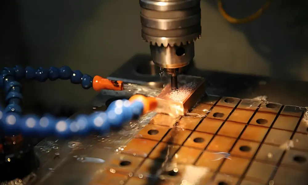
CNC Machining
Computer-controlled milling and turning produce mold plates, pockets for inserts, and runner channels to ±0.01mm. Roughing removes bulk material quickly; finishing passes achieve the dimensional accuracy needed for fit.
CAM software simulates the toolpath before cutting — critical for avoiding collisions in deep cavity pockets and ensuring consistent chip evacuation.
Wire EDM (Electrical Discharge Machining)
EDM cuts hardened steel by controlled electrical spark erosion. It is the primary method for producing cavity and core details that cannot be reached by rotating tools — fine slots, sharp internal corners, and complex parting line profiles.
Slow-wire EDM achieves ±0.002mm on critical dimensions. At Fecision, seven slow-wire EDM machines are dedicated to cavity and insert production. This tolerance is necessary to hold the 0.01–0.03mm cavity/core clearance that prevents flash without causing binding.
Grinding and Polishing
Surface grinding achieves flatness and thickness tolerances on plates and support blocks. Cavity polishing follows a progressive grit sequence — rough stone, fine stone, emery paper, diamond paste — to reach the final SPI surface finish specified.
Mirror-polish cavities (SPI A-1) require manual polishing to Ra ≤0.012µm using 3µm and 1µm diamond paste. This process is done under magnification and takes 6–12 hours for a single cavity face.
Heat Treatment and Surface Coatings
Heat treatment — vacuum hardening followed by double tempering — develops the final hardness of tool steels like H13 and S136. Done after rough machining, before finish machining to final dimensions.
Surface coatings extend component life beyond what steel hardness alone provides:
- DLC (Diamond-Like Carbon): ≥2,200 HV hardness. Applied by PVD. Reduces friction and wear on ejector pins, sliders, and high-contact surfaces. Typical coating thickness: 2–4µm.
- Nitriding: Diffusion process that hardens surface to HRC 65+ to a depth of 0.1–0.3mm. Suitable for ejector pins and guide elements.
- Hard chrome: Electroplated; 0.005–0.05mm thickness. Restores worn dimensions on cavity surfaces. Being replaced by DLC in many applications.
Maintenance and Mold Lifespan
A well-maintained mold outlasts a poorly maintained one by a factor of 2–4 in equivalent shot counts. The investment in routine maintenance returns more than it costs in avoided emergency repairs and scrap.
Cleaning
Regular removal of plastic residue, dust, and contaminants prevents defects and extends mold life. Proper cleaning ensures a smooth molding process and maintains part quality. Clean molds minimize cycle time fluctuations and improve efficiency. Specialized cleaning agents protect delicate surfaces from damage.
Clearing debris from cooling channels allows for efficient heat dissipation and prevents overheating. Blockages can lead to uneven cooling and defects such as warping and deformation. Regular cleaning with flushing solutions maintains optimal cooling efficiency.
Lubrication
Applying grease and lubricants to moving parts such as ejector pins and sliders reduces friction and wear. Proper lubrication prevents sticking, ensures smooth demolding of molded products, and maintains consistent performance. However, excessive lubrication should be avoided to prevent contamination of molded parts.
Regular Inspections
Regular inspections for wear, cracks, and misalignment allow for early detection of potential failures. Identifying worn and damaged parts prevents costly repairs and production delays.
Detailed inspections maintain mold accuracy and product consistency. Addressing common mold problems such as flashing, short shots, and warping requires identifying defective parts and making necessary adjustments.
| Interval | Action | Purpose |
| Every 50,000 shots | Clean vents; polish cavity surface | Prevents burn marks from blocked vents; maintains surface gloss |
| Every 100,000 shots | Inspect guide pins/bushings for wear; check ejector pin lengths | Prevents mold misalignment and flash; catches worn pins before breakage |
| Every 250,000 shots | Replace worn ejector pins; clean cooling channels with flush solution | Maintains ejection force and part quality; prevents channel blockage |
| Every 500,000 shots | Measure cavity dimensions for wear; recoat DLC or nitriding if needed | Ensures dimensional tolerance held; restores surface hardness |
Key Wear Indicators
- Flash on parting line: First sign that guide pins or parting surface steel is wearing. Measure guide bushing bore — replace when clearance exceeds 0.05mm.
- Parts sticking: Ejector pins worn short, draft insufficient, or cooling imbalance causing part to cling to wrong side. Check pin length — pins should protrude 0.1–0.3mm above core surface.
- Burn marks appearing suddenly: Vents blocked by residue. Clean and re-open to 0.02–0.05mm depth. Do not machine deeper or flash will appear.
- Cycle time creeping up: Cooling channel scale buildup. Flush with descaling solution; measure coolant flow rate at entry and exit — more than 10% drop indicates blockage.
Conclusion
Every defect in an injection-molded part traces back to a component condition or design decision in the mold. Burn marks come from blocked vents. Flash comes from worn guide elements or insufficient support. Part sticking comes from inadequate draft or worn ejector pins. Dimensional variation comes from unbalanced cooling.
Understanding what each component does — and what happens when it fails — is what separates a productive troubleshooting conversation from hours of machine parameter adjustment that achieves nothing.
Fecision specializes in injection mold parts manufacturing. We design and build injection molds with in-house CNC, slow-wire EDM machines, and DLC-coated tooling for long-run programs. If you are in the tooling design or supplier evaluation stage, our engineering team provides DFM review as part of the quoting process.
Frequently Asked Questions
What material should I specify for my cavity and core inserts?
For volumes under 100,000 shots with non-abrasive resins: P20 pre-hardened steel is cost-effective and ready to machine without post-treatment hardening. For volumes above 500,000 shots or glass-filled materials: H13 hardened to HRC 48–52. For medical devices or applications running PVC: S136 stainless for corrosion resistance.
What is the difference between a cold runner and hot runner?
A cold runner solidifies between cycles and ejects with the part — creating 15–30% waste by shot weight. A hot runner maintains the melt at temperature throughout the cycle, eliminating runner waste and reducing cycle time by 20–30%.
How many ejector pins does my part need, and where should they be placed?
Minimum four ejector pins for parts wider than 100mm — to distribute ejection force without tilting the part. Pins should be placed within 2× the wall thickness of ribs, bosses, and features that generate adhesion forces.
How do I know if my mold’s cooling system is working well enough?
Three indicators: consistent cycle time (cooling time should not vary more than ±1 second at stable production), uniform part temperature at ejection (measured by infrared thermometer on the core surface immediately after part removal), and dimensional stability (critical dimensions should not drift across a production run as the mold heats up).
When should I choose a slider versus a lifter for an undercut feature?
Sliders handle external undercuts — side holes, hooks, snaps, and through-features accessible from the outside of the part. Lifters handle internal undercuts — inside clips, internal threads, and snap grooves that are trapped between the core and the cavity.
References & Authoritative Sources
All sources publicly available. Accessed April 2026.
[1] Wikipedia. ‘Injection Moulding.’ (Mold types, material selection for mold construction, steel hardness ranges, general process parameters.) https://en.wikipedia.org/wiki/Injection_moulding
[2] Xometry. ’10 Parts of an Injection Molding Machine.’ (Cavity/core component functions; surface finish specifications; guide system requirements.) https://www.xometry.com/resources/injection-molding/injection-mold-components/


