

| Insert molding mold design places a pre-made metal, ceramic, or plastic insert into a mold cavity before injection, bonding it permanently to the surrounding resin in a single cycle. Critical design variables include: minimum plastic wall ≥ 0.8 mm around any insert face, boss OD ≥ 1.8× insert OD, gate placement for compressive flow, and insert preheating to 120–150°C to prevent interfacial voids. |
A shift of even 0.05 mm in insert position — smaller than a human hair — can compromise a leak-proof medical valve or misalign a connector pin array beyond acceptable tolerance. The sections below cover material pairing, five pre-design checks, and nine quantified geometry rules.
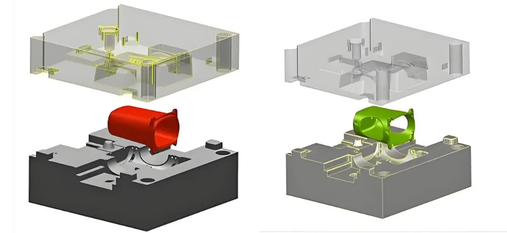
What Is Insert Molding?
Insert molding is a single-cycle injection molding process where a pre-formed insert — metal, ceramic, glass, or another plastic — is placed inside the mold cavity before the injection stroke. Molten resin flows around and captures the insert, creating one inseparable component after cooling.
The structural advantage over post-assembly methods is permanent: a molded-in insert is encapsulated under compression from polymer shrinkage, while a press-fit insert relies only on interference fit that relaxes under thermal cycling. Pull-out force for a correctly designed molded-in threaded brass insert in PA66 typically exceeds 2,000 N — compared to 400–600 N for an equivalent press-fit installation in the same material.
Insert molding also eliminates a secondary assembly operation entirely. The finished part exits the press with the insert captured, correctly positioned, and ready for downstream assembly — with no handling step between insert placement and part completion.
Insert Materials: Five Metals and When to Use Each
The insert must withstand both the mechanical stress of insert placement and the thermal and pressure conditions during injection. The five materials below cover the production range for precision insert molding programs.
| Insert Material | Key Properties | Typical Applications | Bonding/Surface Notes |
| Brass | Excellent heat conductivity; cost-effective; self-lubricating alloy | Threaded inserts, electrical connectors, precision bushings | Knurled surface for mechanical interlock; good adhesion to PA66 and PBT |
| Stainless Steel 316L | Superior corrosion resistance; withstands autoclave cycles at 121–134°C | Medical device housings, cannula handles, surgical instrument grips | Mechanical undercut required; chemical passivation not needed when fully encapsulated |
| Aluminum 6061 | Lightweight (2.7 g/cm³); excellent thermal management; anodizable surface | LED housings, heat sink components, aerospace latches | Anodized surface increases surface energy and pull-out resistance by ~40% |
| Titanium Grade 5 | Biocompatible (ISO 10993); highest strength-to-weight ratio; non-magnetic | Implant-adjacent surgical tools, MRI-compatible devices | Surface passivation step eliminated when overmolded with PPSU or PEEK |
| MIM Ceramics | Electrical insulation (volume resistivity >10¹⁴ Ω·cm); CTE-matched to LCP | RF connectors, high-frequency electronic insulators | High-performance polymer pair required; verify CTE match before tooling |
Material pairing governs more than bond strength. The coefficient of thermal expansion (CTE) differential between the insert and the surrounding plastic determines residual stress after cooling. This differential must be accommodated in the boss wall thickness calculation.
Plastic Resins: What Bonds Well and Why
The injected resin must satisfy three simultaneous requirements: sufficient flow to encapsulate the insert completely, thermal and chemical compatibility with the insert surface treatment, and the mechanical properties the finished part needs in service. The five resins below are the most commonly specified in precision insert molding programs.
| Plastic Resin | Key Properties | Typical Applications | Processing Notes |
| PA66+GF30 | High creep resistance around metal threads; HDT 250°C (1.82 MPa); Cpk >1.67 on critical thread engagement zones | Metal thread housings, industrial connector housings, structural brackets | High-load industrial and electronics programs; pre-dry 80°C/4h mandatory |
| PBT | Low moisture absorption (<0.08% at 24h); excellent dielectric stability; dimensional consistency | Sensor encapsulation, electronics housings, precision enclosures | GF30 grade reduces shrinkage to 0.3–0.8% for insert proximity geometry |
| LCP | Mold shrinkage <0.1% (flow direction); Dk 3.2–3.5; very low CTE | Micro-pin connectors, RF components, sub-0.5mm pitch housings | Single gate mandatory; weld line strength lower than base resin — gate position critical |
| PPSU | Steam sterilizable at 134°C for 1,000+ cycles; IR-transparent; high hydrolytic stability | Medical device housings, reusable surgical instrument handles | Barrel temp 360–390°C; pre-dry 150°C/4h; mechanical interlock on insert required |
| TPE-S | Shore A 30–90 configurable; overmoldable onto PP/PA substrates; chemical resistance | Ergonomic grips, medical device handles, sealed housings | Single-shot over rigid insert or substrate; verify adhesion to specific base resin |
Processing temperature determines resin eligibility as much as mechanical properties do:
- PPSU’s barrel temperature places it beyond the safe range for brass inserts without preheating control, and aluminum inserts must be evaluated for annealing effect at this temperature.
- LCP’s extremely fast fill time (0.2–0.3 second cavity fill) requires the insert locating features to hold position under the dynamic pressure transient — a requirement that affects both locating pin tolerance and insert preheating temperature.
Surface Preparation and Bond Promoters
When the natural bond between the resin and insert surface is insufficient for the pull-out and torque requirements, surface preparation increases adhesion through mechanical, physical, or chemical mechanisms. The table maps all four standard approaches with their engineering constraints.
| Method | Mechanism | Engineering Notes |
| Chemical Etch (acid bath) | Creates micro-roughness Ra 1.6–3.2 µm on metal surface; increases bonding contact area | Increases pull-out force 25–50% vs smooth surface. Standard for stainless steel and titanium inserts in medical programs. Verify etchant compatibility with base metal before production. |
| Knurl Pattern | Mechanical interlock machined into insert OD; straight, diamond, or cross-hatch pattern | Diamond knurl at 0.5–0.8 mm pitch is standard for threaded brass inserts. Provides primary torque and pull-out resistance independent of adhesive chemistry. Specify knurl depth 0.3–0.5 mm. |
| Plasma Activation | Raises insert surface energy from ~30 to >60 mN/m; improves melt wetting | Particularly effective for aluminum and PEEK-to-metal interfaces. Effect degrades within 48 hours of treatment — insert loading must follow plasma activation within the same production shift. |
| Silane Coupling Agent | Bifunctional molecules bond inorganic insert surface to organic polymer matrix covalently | Used where mechanical interlock alone is insufficient (smooth-surface ceramics, glass). Select silane chemistry matched to specific resin — aminosilane for PA66; epoxysilane for PBT. |
Surface preparation selection depends on the failure mode being addressed.
- Mechanical interlock (knurl) resists pull-out and torque — the dominant failure modes in threaded inserts.
- Chemical activation (plasma, silane) improves interfacial adhesion against peel and delamination — relevant for flat or smooth-surface inserts where mechanical interlock is not practical.
For maximum performance, combine a mechanical surface (knurl) with a chemical activation (plasma or silane) applied immediately before loading.
Five Pre-Design Checks before Insert Molding Tooling
Before designing the insert mold, you must perform a number of checks. These checks address failure modes that cannot be corrected after tooling is committed. Each one should be completed and documented before the mold design is released for machining.
Check 1 — Insert Strength vs. Peak Cavity Pressure
The insert’s compressive yield strength must exceed the peak cavity pressure during injection — typically 70–130 MPa for standard engineering resins, up to 160 MPa for fiber-filled high-viscosity grades.
A brass insert in a thin section subjected to high injection pressure will deflect, producing dimensional error on the finished part. Verify using the insert’s cross-sectional moment of inertia against the expected peak pressure from mold flow simulation.
Check 2 — CTE Mismatch and Residual Stress Budget
Calculate the differential thermal contraction between insert and resin during cooling from melt temperature to ambient. The design should provide minimal interference after cooling to limit the opportunity of creating stress cracks in the plastic. If the calculated hoop stress in the boss wall exceeds 60% of the resin’s tensile strength, increase boss OD or select a lower-CTE resin.
Check 3 — Production Volume and Loading Strategy
Volume determines whether hand-loading with a jig, or robotic automated loading with a heated insert station, is economically justified. At volumes below 50,000 per year, hand-loading with a positioning jig and calibrated insert tray is typically more economical. Above 100,000 per year, a robotic cell with in-mold vision confirmation of insert position before clamp closes reduces rejects from misloaded inserts to near zero.
Check 4 — Design FMEA for Failure Mode Priority
Conduct a Design FMEA before specifying tolerances. Common insert molding failure modes ranked by Risk Priority Number (RPN): insert misalignment (RPN 400–500), interfacial void from cold insert (RPN 350–450), and pull-out under cyclic load (RPN 300–400).
FMEA findings drive tolerance specification — a misalignment mode with high RPN justifies tighter locating pin clearance and in-mold vision inspection, which would be cost-unjustified if RPN were low.
Check 5 — Regulatory and Material Certification Requirements
Material selection must satisfy the regulatory framework for the application before any other selection criterion.
- Medical device components with direct patient contact require biocompatibility assessment per ISO 10993-1: 2023. [1]
- Stainless steel 316L is the standard choice for components in contact with bodily fluids.
- Titanium Grade 5 is specified where MRI compatibility or implant-adjacency is required.
Confirming this requirement first prevents redesign after material selection is locked.
Nine Design Rules for Insert Molding
Once you’ve settled on materials and passed your pre-design checks, you need to apply specific geometric rules for insert mold. These rules ensure a strong bond, proper material flow, and clean mold release.
Minimum Wall Thickness Around Insert
It is imperative to maintain the thickness of plastic wall surrounding any insert face ≥ 0.8 mm — ≥ 1.5 mm for structural loads. Walls below 0.8 mm cannot absorb the residual melt pressure after gate freeze-off and will show sink marks on the exterior surface. For thermally conductive inserts (brass, aluminum), add 0.2 mm to compensate for localized rapid cooling at the insert interface.
Corner Radii
All internal corners: ≥ 0.5 mm radius minimum; ≥ 1.0 mm recommended for structural zones. Sharp corners at insert interfaces concentrate stress in the polymer at exactly the point where residual mold stress and thermal mismatch stress already coexist, which greatly increases the likelihood of plastic cracking right near the insert. A 0.5 mm radius reduces peak stress concentration by approximately 3×.
Draft Angles
A moderate draft angle on the plastic boss is often needed. This keeps the insert from backing out after molding, while still letting the finished part eject cleanly from the cavity. You need just enough grip and just enough release.
Plastic boss encapsulating a cylindrical insert: 0.5–1.0° draft on the boss exterior for clean ejection. Zero draft on the insert-contact bore to maintain dimensional register. Deep boss features (> 5× diameter): increase to 1.5–2.0° on external surfaces.
Knurl Geometry
The right knurl pattern on the insert is key to a strong hold. A proper knurl significantly increases the pull-out and torque resistance of the insert compared to a smooth surface. There are different patterns, so choose one suited to your part’s stress profile.
- Straight knurl: resists axial pull-out.
- Diamond knurl: resists both pull-out and torque — preferred for threaded inserts.
Knurl pitch is suggested at 0.5–0.8 mm; depth 0.3–0.5 mm. Coarser knurl (pitch > 1.0 mm) creates thin plastic bridges that crack under thermal cycling.
Gate Placement
Gate location affects the flow of the molten plastic and the final weld line position. Try to place the gate to create compressive flow around the insert — not tensile. Flow arriving parallel to the insert axis, from one side, creates a weld line on the opposite side at the weakest location. Gate positioned to produce a circumferential flow front around a cylindrical insert achieves maximum bond strength. Keep gate vestige ≥ 3 mm from insert edge.
Anti-Rotation Features
Cylindrical inserts require at least one flat, slot, or spline to prevent rotation under torque. A single flat on a 6 mm diameter insert increases torque resistance by 35–60% versus a fully round insert. For precision alignment (sensor housings, connector contacts), design a D-profile or twin-flat locating feature.
Boss OD Sizing
The boss diameter of the plastic housing should be proportionally larger than the insert diameter. Minimum boss OD = insert OD × 1.8 for brass; × 2.0 for stainless steel. This ratio ensures the plastic wall can absorb differential thermal shrinkage stress without cracking. Undersized bosses (ratio < 1.5) are the most common cause of stress cracking at insert-plastic interfaces after thermal cycling in field service.
Insert Preheating
Preheat metal inserts to 120–150°C before loading. Cold inserts (room temperature) cause the melt front to freeze prematurely at the insert surface, creating voids at the interface and dramatically reducing pull-out force. An in-mold heated insert collet or separate preheating station (±5°C control) achieves this consistently.
Locating Pin Tolerance
Insert locating pin clearance: +0.02/−0.00 mm (H7 fit). Tighter than this risks insert cracking from thermal expansion during injection; looser allows misalignment that exceeds acceptable tolerances on finished-part pin position. Verify fit after first-article CMM inspection.
Why Insert Molding Outperforms Post-Assembly
Insert molding is more than just a joining process; it’s a method that delivers performance and cost benefits that traditional assembly simply cannot match. It streamlines your manufacturing process.
Higher Pull-Out and Torque Resistance
Encapsulation under shrinkage compression produces pull-out forces of 1,500–2,500 N for a standard M4 threaded brass insert in PA66 — compared to 400–700 N for an equivalent press-fit installation. The plastic shrinks onto the knurled insert surface during cooling, locking it in place with a force that increases with every thermal cycle rather than decreasing as press-fit interference does.
Eliminated Secondary Operations
Each secondary operation in a post-assembly process carries its own cycle time, handling risk, and tolerance stack-up. Replacing three assembly steps (press insert, thread engagement, seal application) with a single molded-in insert removes three compounding tolerances from the assembly stack and eliminates the labor associated with each step.
Miniaturization Capability
Features that cannot be reliably assembled at small scale — metal contacts in a 0.5 mm pitch connector housing, metallic shielding in a 3 mm diameter catheter handle — are achievable through insert molding. The insert is positioned precisely by the mold locating features, and the encapsulating resin fills around it without the tolerance accumulation that fastener assembly introduces.
Sealing Without Gaskets
IP67/IP68 sealing — 1 meter water immersion and 1.5 meter immersion respectively — is achievable through insert molding without a separate gasket or sealant. The resin flows into every surface irregularity on the insert and forms a chemically or mechanically bonded seal. This seal does not depend on gasket compression force or adhesive cure quality — it is intrinsic to the geometry and material bond.
Reduced Part Count and BOM Complexity
Integrating a metal insert and plastic housing into one component eliminates fasteners, adhesives, and assembly fixtures from the bill of materials. This reduction simplifies supply chain management, reduces incoming inspection points, and removes tolerance stack-up at every eliminated interface. For medical device programs, fewer components means a shorter biocompatibility assessment list and a simpler regulatory dossier.
Applications of Insert Molding by Industry
Since plastic insert molding is highly flexible, it will be necessary in an extensive range of high-tech and high-demand industries. You always see and use these parts in your daily life.
Medical Device Housings
Metal electrode contacts, fluidic fittings, and structural frames encapsulated in medical-grade PPSU or PEEK are standard for diagnostic instruments and surgical devices. The insert molded assembly survives 1,000+ autoclave cycles at 134°C without dimensional change at the insert-plastic interface — a requirement impossible to meet with adhesive-bonded or press-fit assemblies that relax under thermal cycling.
Consumer Electronics Connectors
Metal contact pins, shielding cans, and antenna elements encapsulated in LCP or PA9T housings achieve pin-to-pin positional accuracy of ±0.01 mm — required for 0.3–0.5 mm pitch board-to-board connectors. Insert molding eliminates the air gap that manual soldering or press-fit assembly introduces at the metal-plastic interface, reducing signal path discontinuity in high-frequency applications above 10 GHz.
Aerospace Structural Latches
Polymer-metal hybrid latches produced by insert molding meet UL 94 V-0 flammability requirements and achieve specific strength (strength per unit weight) comparable to aluminum alloy — at significantly lower total component weight. The integration of the metal retention feature directly into the polymer latch body eliminates a fastener joint that would otherwise be subject to vibration-induced loosening in flight environments.
Industrial IoT Connector Housings
Threaded metal inserts in a robust GF-PBT housing allow these connectors to achieve IP67 sealing and 10,000+ mating cycles — both requirements that a purely plastic housing cannot satisfy without metal reinforcement at the thread interface. The single-piece molded construction simplifies field installation and eliminates the separately sealed insert that can be incorrectly installed by field maintenance personnel.
Conclusion
Insert molding mold design translates a three-dimensional material pairing into a set of quantified geometric constraints. Wall thickness, boss OD, gate location, and insert preheating temperature are not design preferences — they are calculable specifications that determine whether the finished part survives its service life or fails at the insert-plastic interface.
The five pre-design checks address failure modes that tooling cannot correct: CTE mismatch stress, insert deflection under cavity pressure, and regulatory material requirements. The nine geometry rules provide the numeric specifications that convert design intent into a mold that performs consistently across production volume.
Fecision offers complete injection molding services and takes your product from a rapid prototype to high volume production. We handle complex projects that include overmolding and specialized insert molding services, while maintaining high repeatability and material compatibility. Our state-of-the-art facilities combine advanced machinery and continuous quality control to deliver precise, ready-to-use components efficiently.
Contact Fecision now to discuss your custom project! Upload your drawing and part requirements today and let Fecision turn your custom insert molding project into a distinct market-ready advantage.
Frequently Asked Questions
What is the minimum wall thickness around a metal insert?
Minimum 0.8 mm plastic wall surrounding any insert face; 1.5 mm minimum for structural load-bearing zones. Walls below 0.8 mm cannot absorb residual melt pressure after gate freeze-off and develop sink marks on the exterior surface. For thermally conductive inserts (brass, aluminum), add 0.2 mm to the minimum to compensate for localized rapid cooling at the insert-plastic interface.
How do you prevent stress cracking around an insert after molding?
Three simultaneous controls: (1) boss OD ≥ 1.8× insert OD to accommodate differential thermal shrinkage; (2) all internal corners at insert-plastic interfaces ≥ 0.5 mm radius to eliminate stress concentrators; (3) preheat inserts to 120–150°C before loading to prevent premature melt freeze at the interface. Stress cracking typically appears after thermal cycling in field service, not at first-article inspection — these controls must be designed in, not detected in QC.
What pull-out force does insert molding achieve versus press-fit?
A correctly designed molded-in M4 threaded brass insert in PA66 achieves 1,500–2,500 N pull-out force — compared to 400–700 N for an equivalent press-fit installation. The molded-in insert is captured under compression from polymer shrinkage during cooling, and this compressive load increases with thermal cycling rather than relaxing as press-fit interference does under the same thermal loads.
Which metals are compatible with PPSU for medical insert molding?
Stainless steel 316L and titanium Grade 5 are the standard choices for PPSU insert molding in medical applications. Both survive PPSU’s barrel temperature (360–390°C) without annealing or dimensional change. Titanium Grade 5 is specified where MRI compatibility or ISO 10993 implant-adjacent biocompatibility is required. Brass is not recommended above 340°C barrel temperature — it approaches its annealing threshold and may soften under sustained thermal exposure.
How does gate placement affect bond strength in insert molding?
Gate placement determines flow front geometry at the insert surface. A gate positioned to create circumferential flow around a cylindrical insert — where melt arrives from all directions simultaneously — produces compressive hoop stress on the insert during packing and maximizes pull-out resistance. A gate creating a unidirectional flow front produces a weld line on the downstream side of the insert, where the two converging flow fronts meet at reduced molecular diffusion — the weakest location in the finished part.
References
Accessed May 2026.
[1] ISO 10993-1:2023 — Biological Evaluation of Medical Devices, Part 1: Evaluation and Testing within a Risk Management Process. https://www.iso.org/standard/68936.html
[2] Rosato, D.V. & Rosato, M.G. Injection Molding Handbook, 3rd Edition. Kluwer Academic Publishers, 2000.
[3] ASTM B211 / B211M — Standard Specification for Aluminum and Aluminum-Alloy Bar, Rod, and Wire. https://www.astm.org/b0211_b0211m-19.html


