

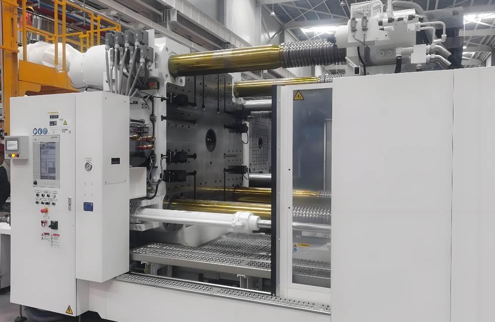
Large part injection molding (also called large tonnage molding) is a specialized manufacturing process for producing oversized plastic components exceeding 500mm in any dimension or requiring clamping force above 500 tons.
Unlike standard injection molding, this process demands precise machine tonnage calculation, extended cooling strategies, and structural DFM principles to prevent warpage in large surface area parts used in automotive panels, industrial equipment housings, and material handling containers.
This guide covers the essentials of large-part injection molding. You will learn its definition, the dominant processes and materials for molding large plastic parts, and the key industries that use these components every day.
What Is Large Part Injection Molding?
Large part injection molding, or large-tonnage molding requires much more than just getting a bigger machine. It refers to the production of plastic components with projected areas exceeding 300 square inches or weights above 1kg, utilizing machines with clamping force ranging from 500 to 1,300+ tons. These components feature thick wall sections (typically 3-6mm), large surface areas, and structural reinforcement requirements that standard molding equipment cannot accommodate.
The core process forces melted plastic into a mold cavity under high pressure. Enough clamping force will be needed to keep the mold halves shut against that pressure. This technology is used across many industries to create everything from vehicle dashboards to large industrial containers.
Technical Thresholds
- Machine Tonnage: ≥500 tons (industry standard entry point for “large part” classification)
- Part Dimensions: Often exceed 500mm × 500mm footprint
- Shot Volume: 3,000g–15,000g depending on wall thickness and geometry
- Tooling Weight: Molds frequently exceed 5,000kg, requiring overhead cranes
Key Differentiators from Standard Molding
- Clamping Force Distribution: Large platens (1,000mm × 1,000mm+) require uniform force distribution to prevent flash
- Cooling Time Dominance: Accounts for 60–70% of cycle time in thick-wall sections
- Material Shrinkage Control: Linear shrinkage rates compound over large dimensions, requiring precise process control
Machine Tonnage Calculation: The Engineering Formula
Selecting the correct machine tonnage is critical—insufficient clamping force causes mold separation and flash, while excessive tonnage wastes energy and accelerates mold wear.
The Tonnage Calculation Formula
Tonnage=Projected Area×Clamp Factor×Safety Factor
Step 1: Calculate Projected Area
- Measure the largest silhouette of the part (and all cavities) in the direction of clamp movement
- Include runner system area (cold runners add 15–25% to projected area)
- Do not subtract holes unless created by mechanical shut-offs
Step 2: Select Clamp Factor (Material-Specific Pressure)
Clamp factor represents cavity pressure required based on material viscosity and wall thickness:
| Material | Wall Thickness 2-3mm | Wall Thickness 4-6mm | Clamp Factor Range |
|---|---|---|---|
| PP/PE (Low viscosity) | 2.5–3.0 tons/in² | 2.0–2.5 tons/in² | 2–4 tons/in² |
| ABS/PS (Medium viscosity) | 3.0–4.0 tons/in² | 2.5–3.0 tons/in² | 3–5 tons/in² |
| PC/Nylon (High viscosity) | 4.0–5.0 tons/in² | 3.5–4.5 tons/in² | 4–8 tons/in² |
| Glass-Filled (Abrasive/High flow resistance) | 5.0–6.0 tons/in² | 4.5–5.5 tons/in² | Add 20–30% to base |
Step 3: Apply Safety Factor
- High-volume production: 1.10–1.15 (10–15%)
- Prototype/development: 1.20–1.30 (20–30%) to protect tooling from pressure spikes
Calculation Example: For an automotive interior panel (ABS, 4mm wall, projected area 400 in²): 400 in2×3.0 tons/in2×1.15=1,380 tons required
Machine Specification Checklist Beyond Tonnage
Large parts require verification of additional machine constraints often overlooked
| Parameter | Specification Requirement | Risk if Inadequate |
|---|---|---|
| Tie-bar Spacing | Must accommodate mold width + 200mm clearance | Mold cannot be installed |
| Platen Size | Minimum 1.5× projected mold dimension | Uneven clamping force distribution |
| Daylight (Opening Stroke) | ≥2× mold height + ejection stroke | Insufficient space for part ejection |
| Shot Capacity | 20–80% of machine barrel capacity | Material degradation (if >80%) or inconsistency (if <20%) |
| Plasticizing Rate | Must melt required volume within cycle time | Extended cycle times |
| Ejection Force | 5–10% of clamping force minimum | Part sticking in large deep-draw molds |
Large Part Injection Molding Processes
Here you’ll find the methods used most for oversized components: the fundamental cycle, specialized molding techniques, and secondary steps to finish your large injection molded parts.
The Standard Injection Molding Cycle for Large Parts
This is the important and sequential set of actions that are performed to create a single large plastic part in a completed cycle.
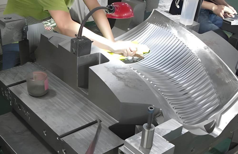
Step 1: Mold Preparation & Clamping
First, the mold must be cleaned and set up perfectly. Then, the two mold halves are securely clamped together with immense force. You need a large-tonnage machine to withstand the extremely high pressures of the injection process.
Step 2: Injection & Filling
Next, the plastic resin is melted and then injected into the mold cavity at very high pressure. This step is critical to ensure that the material fills the entire, often complex, cavity and accurately replicates your part design.
Step 3: Cooling & Solidification
Once filled, the molten plastic inside the mold is allowed to cool down and solidify. For your plastic injection molding large parts, this phase takes a long time. It is the most critical step to prevent warping and to guarantee dimensional stability.
Step 4: Ejection & Post-Processing
When the part is finally cooled, the mold opens, and the finished component is robotically ejected. The part then goes through inspection for any injection molding defects and may require trimming or other simple finishing operations.
Specialized Molding Techniques
A number of advanced techniques, such as sink marks, high weight, and internal stresses, have surfaced to address the challenges of injection molding large flat parts and to ensure your quality requirements are achieved.
Gas-Assist Molding
This advanced method injects pressurized nitrogen gas after the initial plastic shot. This creates hollow channels inside the part and reduces material usage and overall component weight for you. The gas will also eliminate sink marks in thick areas and improve dimensional stability, which is vital to large panels, handles, and any component requiring high integrity.
Structural Foam Molding
The process mixes a special foaming agent with the polymer to create your part, with a solid outer skin and a lightweight, rigid foam core. This provides excellent stiffness. The technique is perfect for you when producing very large components that require high stiffness but low internal stress, like industrial pallets or machine housings.
Finishing and Alternative Processes
After molding, your large injection molded parts often require finishing. Also, for certain large geometries, an alternative production method may be more suitable than injection molding.
Post-Processing and Decoration
This critical stage includes operations like pad printing. This method uses a flexible silicone pad to effectively transfer detailed graphics and logos onto surfaces. This is perfect for adding branding or labels to the irregular surfaces of large components like bins and containers.
Blow Molding as a Complementary Technology
While it is not an injection molding process, blow molding is also very relevant for larger hollow parts. This involves inflating a heated plastic parison inside a mold. It forms seamless, hollow parts like large tanks or drums, which offer a very economical approach to those specific geometries.
Critical Process Parameters for Large Parts
Large part molding requires tighter process control than standard molding due to differential cooling rates across thick sections and large surface areas.
Temperature Control Strategy
Melt Temperature Management:
- Barrel Profile: Use 5-zone temperature control (feed zone to nozzle)
- Residence Time: Critical for large shots—keep <5 minutes to prevent degradation
- Typical Ranges: ABS: 230–270°C; PC: 280–320°C; PP: 200–240°C (large parts require upper range for flow)
Mold Temperature Uniformity:
- Critical Requirement: Maintain ±5°C across entire cavity surface to prevent warpage
- Large Part Recommendation: 60–80°C for ABS/PC (higher than standard to improve flow in long flow paths)
- Cooling Channel Design: Use conformal cooling for deep sections; straight drilling creates hot spots
Pressure Profile Optimization
Injection Pressure:
- Calculation: 15,000–25,000 psi (100–170 MPa) for large parts with long flow lengths
- Multi-stage Profile: Fast fill (70% volume) → Slow pack (remaining 30%) to prevent overpacking at gates
Holding/Packing Pressure:
- Duration: Hold until gate freeze (typically 8–15 seconds for 4mm wall thickness)
- Pressure Level: 50–70% of injection pressure to compensate for volumetric shrinkage
- Large Part Risk: Excessive holding pressure causes residual stress and warpage in large flat areas
Cooling Time Calculation (Critical for Large Parts)
Cooling time represents 60–70% of total cycle in large part molding. Use this formula:
Cooling Time (seconds)=Mold Temperature Efficiency/(Wall Thickness (mm)2×Material Factor)
Material Factors: PP/PE: 2.5–3.0; ABS: 3.0–3.5; PC: 3.5–4.0
Example: 5mm thick ABS part: 25×3.2/1.0=80 seconds cooling time
Cooling Strategy for Large Parts:
- Thick Wall Sections (>6mm): Use bubblers or baffles in cores to ensure center cooling
- Warpage Prevention: Differential cooling (mold halves at different temperatures) can counteract warpage tendency
- Cycle Optimization: Extend cooling 20% beyond calculated minimum to ensure dimensional stability upon ejection
Design for Manufacturability (DFM) for Large Components
Large parts require specialized DFM rules beyond standard injection molding guidelines.
Wall Thickness & Geometry
Uniformity is Critical:
- Recommended Range: 3.0–5.0mm for structural large parts
- Transition Rules: Changes in wall thickness must use 3:1 taper ratios to prevent sink marks
- Thick Sections: Bosses and mounting points (>6mm) require core-outs to reduce sink and cycle time
Corner Radii Specifications:
- Internal Radius: Minimum 0.5× wall thickness (ideally 1.0× for large parts)
- External Radius: Internal radius + wall thickness
- Sharp Corner Risk: Stress concentrations in large parts lead to cracking under load due to polymer orientation stresses
Draft Angles for Deep Draws
Large parts often feature deep walls (150mm+):
- Standard Draft: 1.0–1.5° per side
- Deep Draws (>200mm): 2.0–3.0° to prevent ejection damage
- Textured Surfaces: Add 1.0° per 0.025mm texture depth (SPI C3 finish requires additional 3°)
Rib Design for Stiffness
Large flat parts require ribs to prevent warpage and flexure:
- Thickness: 0.5–0.7× wall thickness (thicker ribs cause sink marks)
- Height: ≤3× wall thickness (taller ribs difficult to cool)
- Draft: 0.5° minimum on ribs to prevent sticking
- Spacing: 2–3× wall thickness between ribs for uniform cooling
Parting Line Strategy
For large parts, parting line location affects both aesthetics and tooling cost:
- Avoid: Parting lines on visible cosmetic surfaces if possible
- Recommend: Place on natural geometric breaks or bottom edges (LEGO brick strategy)
- Complex Geometry: Large parts often require side actions (slides) for undercuts—each slide adds $5k–$15k to tooling cost
Common Defects in Large Part Molding & Solutions
| Defect | Cause | Solution |
|---|---|---|
| Warpage | Differential cooling rates across large surface | Increase mold temperature uniformity; use differential cooling (core vs. cavity); add stiffening ribs |
| Sink Marks | Thick sections cooling slowly | Core out thick bosses; reduce wall thickness variation; increase holding pressure time |
| Flash | Insufficient clamp tonnage or worn platens | Recalculate tonnage with 20% safety factor; check platen parallelism (must be within 0.05mm) |
| Short Shots | Inadequate injection pressure for long flow | Increase melt temperature; optimize gate location; increase injection speed (shear heating improves flow) |
| Jetting | High-speed injection into thick sections without impingement | Use multiple gates; reduce injection speed initially; ensure melt impinges on cavity wall |
| Weld Lines | Flow fronts meeting at thin sections | Increase melt/mold temperature; move gate location; add venting at weld line location |
Materials Used for Large Injection Molded Parts
Selecting a resin is also an important factor in making sure your final part meets performance demands. The following is a list of common materials for high-performance large-scale projects.
High-Density Polyethylene (HDPE)
This versatile, economical thermoplastic has excellent chemical resistance and high resistance to impact. It is a semi-crystalline material with an excellent strength-to-density ratio, meaning that it is strong and durable, and is suitable for heavy-duty applications.
The excellent flow properties of HDPE are particularly beneficial when filling your large mold cavities. Due to its robust, weather-resistant properties, HDPE is used in the production of plastic molding large parts, for example, industrial pallets, storage containers, outdoor furniture, etc.
Acrylic (PMMA)
Acrylic is a transparent, glass-like plastic. You might know it by the brand name Plexiglas. It has excellent optical clarity, adequate rigidity, and excellent resistance to weather exposure.
It will not yellow or degrade from UV light exposure, making it a great option for outside usage. PMMA can be seen in large light covers, protective transparent shields, and architectural panels when clarity is very important.
Nylon (Polyamide – PA)
Nylon is a strong engineering thermoplastic that provides excellent toughness, wear resistance, and thermal stability. High mechanical strength and excellent resistance to abrasion are also provided.
Glass fibers are commonly used to reinforce nylon to greatly improve its stiffness and heat resistance, making nylon perfect for demanding structural components, including plastic injection molding large parts of an automotive engine, and large mechanical housings.
Structural Foam Materials
This is a unique process where a foaming agent is mixed with the polymer. It creates a distinct structure. The resulting part has a solid outer skin and a microscopically lightweight foam core.
Structural foams have a very high stiffness-to-weight ratio and low internal stress, leading to excellent stability in dimension. This technique is perfect for you when producing large, rigid structures like machine enclosures and equipment doors.
Material Selection for Large Structural Parts
| Material | Key Properties | Large Part Application | Shrinkage Rate | Mold Temp |
|---|---|---|---|---|
| ABS | Impact resistance, dimensional stability | Automotive interior panels, equipment housings | 0.4–0.7% | 60–80°C |
| PC/ABS | High heat resistance, excellent surface finish | Industrial equipment bezels, medical devices | 0.5–0.6% | 70–90°C |
| PP (Talc-filled) | Stiffness, chemical resistance | Material handling containers, outdoor furniture | 0.8–1.2% | 40–60°C |
| HDPE | Chemical resistance, low cost | Industrial tanks, marine components | 1.5–3.0% | 20–40°C |
| Nylon (GF30) | High strength, wear resistance | Structural machine components | 0.3–0.5% | 80–100°C |
Critical Note for Large Parts: Shrinkage rates compound over large dimensions. A 1% shrinkage rate results in 5mm dimensional variation on a 500mm part—tolerances must account for this anisotropic behavior.
Quality Control for Large Dimensions
Inspection Challenges: Large parts cannot fit in standard CMMs (Coordinate Measuring Machines).
- Solution: Use portable CMM arms or optical scanning (structured light/blue light)
- Tolerance Standard: ISO 2768-m (medium) for dimensions >400mm; ±0.5% or ±2.0mm (whichever is larger)
- Critical Checks:
- Flatness (critical for assembly interfaces)
- Warpage (measure via dial indicators or 3D scanning)
- Sink depth on thick sections (caliper measurement)
Industries and Applications of Large Part Injection Molding
Large part molding is the backbone for numerous sectors, transforming designs into durable, functional components. Let’s look at the key industries that rely on these large-scale parts every day.
Transportation and Automotive Sector
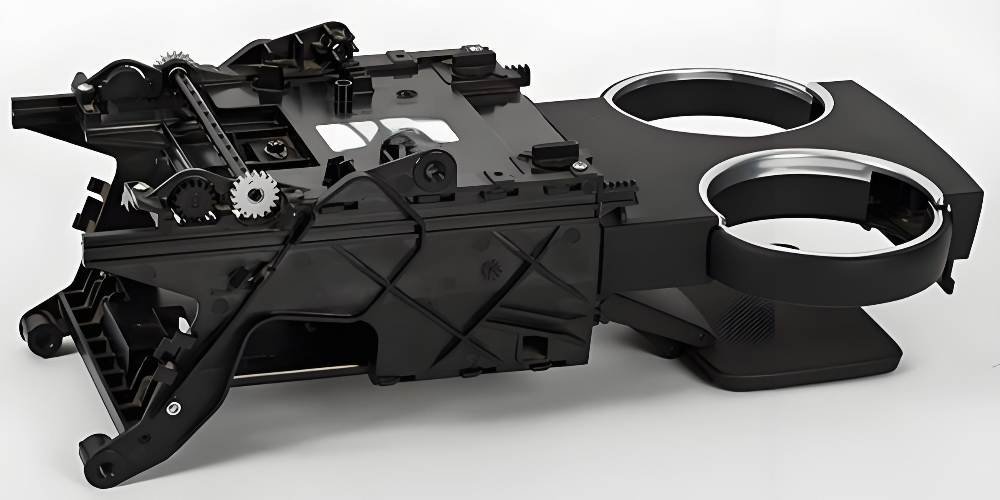
The production of large plastic parts utilizing injection molding is predominantly employed in the automotive sector. Components must adhere to strict design criteria for safety, durability, and aesthetics, requiring producers to ensure precision in the molding process.
Notable applications include both exterior and interior parts, including large bumpers, fenders, grills, door panels, etc. This process allows for the mass production of lightweight parts, directly contributing to better vehicle utility and safety.
Aerospace and Aviation Field
The aerospace industry needs materials that are both strong and light. That’s why we now see more large plastic components in aircraft design.
Usage is expanding from interiors to structural components, including airframe sections, wing components, and engine housings. Advanced polymers match metal’s strength but weigh much less. This cuts fuel burn and reduces how often parts need maintenance.
Consumer and Industrial Electronics
The electronics and robotics manufacturing industries utilize this process to create the large housings and structural frames that provide the outer designs of major appliances and devices. Quality molding is critical for these everyday items.
This includes the outer shells and bases of these appliances, including refrigerators and washing machines. It also includes the internal frames for televisions and other large-screen displays. Injection molding produces robust, aesthetically pleasing casings that protect sensitive components cost-effectively.
Choose a Reliable Large Part Injection Molding Partner
Selecting the right manufacturing partner is as critical as the design itself. A capable large part injection molder ensures not only quality and precision but also project efficiency and cost-effectiveness. Use the following criteria to vet potential suppliers for your large part injection molding companies and your large part injection molding projects.
| Evaluation Criteria | Key Questions & Evidence to Request | Why It Matters for Large Parts |
| 1. Production Capacity | • Can they provide a list and photos of presses (e.g., 2,000 t machines)? • Ask for case studies with “part-in-press” photos of similar-sized components. | Verifies they have the physical machinery (tonnage, platen size) necessary to produce your part without capacity constraints. |
| 2. Tooling Expertise | • Do they own large CNC machines capable of machining 2 m×1.5 m steel blocks (e.g., P20, H13)? • Is mold design and manufacturing handled in-house? | Ensures they can build and maintain the large, high-quality molds required, keeping changes and repairs under one roof for better control. |
| 3. Engineering Support (DFM) | • Request a sample DFM report. It must include gate location, warpage simulation, and cooling analysis. • The absence of weld-line analysis is a major red flag. | A strong DFM process is crucial to anticipate and prevent defects like warping and weak spots in large, complex geometries before cutting steel. |
| 4. Quality Assurance | • Confirm ISO 9001 (or IATF 16949 for automotive) certification. • Is their CMM large enough for your part? Ask for GR&R studies. | Certifications prove a structured quality system. A large CMM and low GR&R ensure your part can be measured accurately and consistently. |
| 5. Vertical Integration | • Are secondary services (painting, welding, assembly) available on-site? • How do they handle logistics and kitting? | On-site services streamline production, reduce shipping damage risk, and significantly shorten lead times for complex assembled products. |
| 6. Sustainability Commitment | • Inquire about closed-loop water systems, regrind protocols, and carbon reduction goals (Scope 2). • Ask if they track ESG metrics. | Demonstrates a forward-thinking partner that can help you meet corporate sustainability targets and comply with evolving OEM requirements. |
Fecision delivers reliable, custom large part injection molding service tailored to your project requirements. Are you ready to convert metal or metal sheet assemblies into lighter, one-piece, large injection molded parts? Contact Fecision directly to discuss your specific large-tonnage requirements!
Frequently Asked Questions
What is the minimum machine tonnage for large part injection molding?
Industry standard defines “large part” molding as 500 tons and above. Parts requiring 1,000+ tons are classified as “heavy tonnage” molding.
How do you prevent warpage in large flat panels?
Warpage prevention requires: (1) Uniform mold temperature (±5°C), (2) Balanced filling patterns (use mold flow simulation), (3) Adequate cooling time (don’t eject too early), (4) Stiffening rib design to resist deformation.
How long does it take to cool a large injection molded part?
Cooling time follows the square of wall thickness. A 5mm thick ABS part requires approximately 80 seconds cooling. Thick sections (8mm+) may require 2–3 minutes cooling time, dominating total cycle.
Can you mold large parts with recycled material?
Yes, but limit regrind to 10–20% of total shot weight. Large parts require consistent melt viscosity—excessive regrind causes flow inconsistencies and potential short shots.


