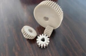
You need precision when thin walls, micro-features, and tight tolerances are the norm. Advanced mold tooling and injection molding tooling choices—steel grade, cooling layout, gate strategy, and in-tool sensors—directly affect cost, quality, and time-to-market.
Complex geometries often demand rotating cores, slides, or hydraulic actuators to form undercuts and fine contacts reliably. Proper runner selection, gate type, and waterline placement control fill, shrink, and warp so parts meet spec and cosmetic goals.
Later sections show how Fecision applies these methods from DFM through qualification so your program scales with confidence and predictable quality.
Why Advanced Mold Tooling Matters for Electrical Terminals and Interconnects
You may deal with thinner walls, delicate ribs, and micro features about your projects. When parts shrink to microns, your injection choices and tool build control whether you meet tolerances and specifications.
Parts landscape
Thin sections and tiny flow paths make balanced cavitation, strong cooling, and correct gate sizing critical. Controlled cooling and simple cavity geometry reduce shrink variability and stabilize part quality.
How decisions matter
Early decisions on mold class, runner strategy, and cavitation cut rework and scrap, lowering total costs and protecting your production schedule. Scientific molding turns guesswork into data: you set fill, pack, and cooling setpoints that repeat from T0 to SOP.
Fecision brings experience building tools for complex parts and glass-filled plastic. That data-first approach shortens development time, preserves part quality, and helps you hit volume ramps with fewer iterations.
Mold Tooling Fundamentals Applied to Sophisticated Electrical Components
Data-driven process controls make complex electrical parts predictable at scale. Scientific practices turn the injection molding process into a repeatable, auditable workflow you can trust for tight tolerances.
Scientific molding
You establish process repeatability by logging cavity pressure curves, cooling setpoints, and pack/hold profiles from studies rather than relying on trial-and-error. That data creates a validated window you can copy across machines and shifts.
Designing for manufacturability
Smart DFM and thoughtful tooling design protect critical mating areas and thin-wall features. Gate location, runner diameter, and vent depth get set to avoid weld lines, short shots, or burn in contact zones.
- Balance cooling and waterline placement to cut warpage around fine ribs and bosses.
- Use interchangeable steel inserts and steel-safe features for fine-tuning without scrapping cores.
- Build a DOE that links material viscosity to process settings to drive high-quality parts.
Work with engineers trained in scientific molding to document specifications and acceptance limits. That discipline keeps your manufacturing process steady and your parts within spec.
Key Challenges
Tight dimensional windows and delicate geometries create the toughest challenges in high-volume connector production. You must balance flow, cooling, and ejection so parts meet spec from first shot to runout.
Tolerance risk factors
Cavitation and uneven cooling drive shrink variability and erode tight tolerances fast. Control cavity-to-cavity balance and pack pressure to keep shrink consistent across thick-to-thin transitions.
Thin sections and delicate features
For thin walls, optimize gate land and venting so molten plastic sweeps micro features without trapping air or causing burns. Use rheology data to check pressure drop along long flow paths and set realistic wall thicknesses.
Surface demands and defect avoidance
Cooling design heavily influences surface finish and warp. Add closer waterlines, conformal channels, or conductive inserts to prevent hot spots. Use shaped ejectors, stripper plates, and slides to protect contacts and avoid stress marks.
Track dimensional capability (Cpk) during trials and validate with thermal cycling and material lot changes to keep your components within spec.
Tooling Architecture Choices for Complex Parts
Architecture choices — from cavity count to runner layout — shape part quality, cost, and ramp speed. Your early selection steers how the injection process behaves and how fast you reach repeatable output.
Selecting cavity strategies
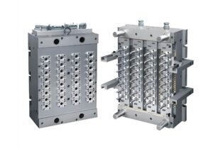
Single-cavity builds suit early validation or large housings where one part must prove out. Move to multi-cavity when demand solidifies to raise throughput without losing capability. Family molds let you produce related parts together and keep mating dimensions consistent.
Consider stack molds for high-volume runs when clamp force or floor space limits you. A well-chosen injection mold layout balances machine capacity and part synchronization.
Runner and gate selection
Choose cold runners for material flexibility and lower up-front cost. Use hot runner systems to cut scrap and improve fill on micro features.
Match gate style to geometry: edge for planar sections, tab to lower shear, submarine for automatic degating, and hot tip for point gates into thin transitions. Proper runner systems support balanced filling and lower cycle variation.
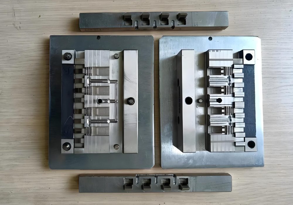
Core, cavity, and ejection design
Engineer cores and cavity shut-offs with vents and wear inserts at high-stress zones like gate lands. Use contoured ejectors and stripper plates to protect sealing faces and fragile bosses.
Slides, lifters, and undercut solutions
Slides and lifters create undercuts and latch features without damaging contacts. Add mechanical or hydraulic actuation for timing and reliability while designing for serviceable inserts to cut downtime and control cycle times.
Materials, Cooling, and Longevity for High-Volume, High-Precision Production
Wear from abrasive resins and uneven cooling are the twin threats to long production life for fine electrical parts.
Steel grades and hardness trade-offs
You pick steel to resist abrasion without making cores brittle. Hard grades fight wear from glass-filled resins, but they can crack under side-loads.
Balance hardness with toughness at shut-offs, slides, and core edges. Use wear inserts or surface coatings at gates and runner areas to extend life while keeping repairable pieces replaceable.
Cooling design and cycle-time control
Place waterlines, bubblers, and baffles to remove heat from deep cores and thin ribs. Conformal cooling follows geometry to cut thermal gradients and lower cycle times.
Validate layouts with moldflow and thermography, then confirm on press with sensors. Monitor cycle times and part temperatures as early indicators of scaling or flow restriction in cooling circuits.
Choosing materials for abrasive applications
For glass-filled and flame-retardant material, plan high-wear zones and specify stainless or treated cooling lines when needed. Add copper-alloy inserts in hot spots to stabilize cosmetic and dimensional quality.
Schedule preventive maintenance by cavity count, abrasiveness, and cycle rates to protect longevity and sustain your production capability.
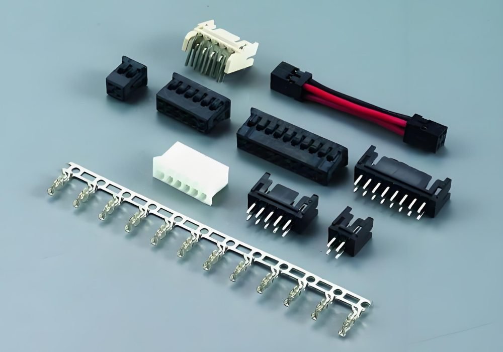
Designing for Electrical Terminals and Interconnects
Getting flow right in micro-features starts with smart gate placement and controlled pressure. Design choices at the cavity level guide how thin webs and contact fingers fill, cool, and hold tolerances.
Gate location, flow, and pressure control
Place gates to sweep along thin ribs and avoid high-shear contact zones. Use edge or tab gates for planar fills, submarine for automatic degating, and hot tip for point fills into tiny transitions.
Balance runner systems and size gates so pressure drop remains low and fill completes without overpacking fragile sections. Monitor cavity pressure traces to set pack and hold so each part replicates consistently.
Alignment, venting, and insert/overmolding tactics
Build alignment keys and datum features into molds to hold pitch and coplanarity across multi-pin arrays. Add vents at end-of-fill and knit lines to avoid trapped gas and burns near conductive inserts.
Preheat and fixture inserts for secure overmolding. Use lifters, stripper plates, or custom ejectors to protect micro features and qualify surface finish for consistent insertion force in high-volume production.
How Fecision Delivers on Complex Electrical Tooling
Fecision turns complex design intent into repeatable production through data-led engineering and practical experience.
- Proven capability with tight tolerances, thin materials, and intricate geometries
Design choices—gate type, runner balance, and waterline placement—are validated to yield high-quality parts and reduce scrap in production.
- From design to scientific qualification for process repeatability
Fecision builds injection molding tooling that anticipates undercuts, multi-form slides, and serviceable inserts to protect critical features over life cycles.
You can reduce costs and time-to-market by pairing architecture choices — multi-cavity, family, or stack — with preventive maintenance and data-driven validation. Work with Fecision to turn complex geometries and thin materials into manufacturable realities with traceable quality and reliable high-volume production.