In the world of precision engineering, a staggering 70% of parts manufactured are rejected due to dimensional inaccuracies stemming from a lack of clear reference points. This is where the concept of a datum comes into play, serving as a foundational element in Geometric Dimensioning and Tolerancing (GD&T).

A datum is a theoretical reference point, line, or plane that acts as the origin for measurements and geometric controls of a part’s features. You rely on datums to establish a coordinate system that ensures the part’s features are correctly oriented and positioned relative to each other.
By defining a datum, you create a common language between design engineers and manufacturing teams, facilitating clear communication of design intent and ensuring parts fit and function as intended in assemblies. This is particularly crucial in precision manufacturing industries like aerospace, automotive, and medical devices, where the accuracy of parts directly impacts the safety and performance of the final product.
The Fundamental Role of Datums in GD&T
Datums play a crucial role in Geometric Dimensioning and Tolerancing (GD&T), serving as the foundation for precision engineering. By providing a consistent reference point, datums ensure that parts are manufactured to specification, enabling precise communication between design and manufacturing teams.
What Is a Datum in Geometric Dimensioning and Tolerancing?
A datum in GD&T is a theoretical point, line, or plane that serves as a reference for the measurement and inspection of parts. It provides a fixed point of reference, allowing manufacturers to ensure that parts are produced within specified tolerances. By establishing a common language, datums facilitate communication between design, manufacturing, and inspection teams.
Why Datums Are Critical for Precision Manufacturing
Datums are critical for precision manufacturing because they ensure that parts fit together as intended, minimizing the risk of misalignment and errors. By providing a reference point for measurements, datums enable manufacturers to produce complex assemblies with accuracy and reliability. This, in turn, ensures that the final product functions as designed, meeting the required specifications and performance standards.
In precision manufacturing, the use of datums helps to reduce manufacturing errors by providing clear references for machining operations, inspection processes, and assembly procedures. By controlling feature location and orientation, datums help to manage manufacturing variations, ensuring that parts will function as intended despite normal manufacturing variability.
The Basic Concepts of Datums in GD&T
In the world of GD&T, datums serve as the foundation for precision manufacturing. Datums are crucial for establishing a common language between designers, manufacturers, and inspectors, ensuring that parts are made to specification.
Theoretical vs. Physical Datum Features
Theoretical datum features are perfect geometric representations, while physical datum features are the actual surfaces or features on a part. Understanding the difference between these two is vital for accurate part manufacturing and inspection. Theoretical datums provide a reference point, whereas physical datums are the real features that are used to establish the datum reference frame.

Degrees of Freedom and How Datums Constrain Them
Datums constrain the degrees of freedom of a part, ensuring it is properly oriented and located. By applying datums, you can limit the movement of a part in various directions, thereby controlling its orientation and position. This constraint is essential for ensuring that parts are manufactured and assembled correctly.
The Datum Reference Frame (DRF) Explained
The Datum Reference Frame (DRF) is a three-dimensional coordinate system established by three mutually perpendicular datum planes. It serves as the foundation for all geometric controls and tolerances, providing a common reference for design, manufacturing, and inspection. The DRF is constructed through the sequential application of primary, secondary, and tertiary datums, each constraining specific degrees of freedom.
By understanding and applying the concepts of datums and the DRF, you can ensure that your parts are manufactured to specification, with clear design intent communicated throughout the manufacturing process.
Primary, Secondary, and Tertiary Datums
To fully constrain a part in 3D space, GD&T utilizes a datum reference frame that consists of primary, secondary, and tertiary datums, each serving a distinct purpose. Understanding the hierarchy and function of these datums is crucial for precision engineering.
Primary Datum: The Foundation
The primary datum is the first datum in the hierarchy and typically constrains the most degrees of freedom, usually three. It is the initial reference point that establishes the part’s orientation in space. For instance, a flat surface might be designated as the primary datum to establish a stable reference plane.
You can think of the primary datum as the foundation upon which the part’s measurement and tolerance framework is built. It is essential to select a primary datum that is accessible, functional, and relevant to the part’s design intent.
Secondary Datum: Further Constraint
The secondary datum further constrains the part, typically limiting two additional degrees of freedom. It works in conjunction with the primary datum to more fully locate the part in space. The secondary datum is crucial for “clocking” or rotationally orienting the part.
For example, a secondary datum might be a surface perpendicular to the primary datum, or it could be a feature like a hole or slot that helps to rotationally orient the part. The choice of secondary datum depends on the part’s geometry and functional requirements.
Tertiary Datum: Complete Positioning
The tertiary datum is the final datum in the hierarchy and typically constrains the last remaining degree of freedom, often a translational movement. It is used when fully constraining the part is necessary, ensuring that it is completely located in 3D space.
A tertiary datum might be a small hole, a slot, or an edge that provides the final point of contact to stabilize the part. For instance, a single point contact on a tertiary datum feature can be sufficient to fully constrain a part, completing the datum reference frame.
The complete datum reference frame, comprising primary, secondary, and tertiary datums, works together to fully constrain all six degrees of freedom, ensuring that the part is precisely located and oriented in space. While three datums are typically required for full constraint, there are special cases where fewer datums may suffice, such as with cylindrical parts where an axis and a plane might be enough.
How Datums Impact Tolerances and Assembly
Datums play a pivotal role in controlling tolerances and facilitating smooth assembly processes. By establishing a common reference point, datums help ensure that parts are manufactured within specified tolerances, which is crucial for their proper assembly and function.
Controlling Feature Location and Orientation
Datums are essential for controlling the location and orientation of features on a part. By referencing a datum, manufacturers can ensure that features such as holes, surfaces, and edges are correctly positioned relative to each other. This is particularly important in assemblies where multiple parts must fit together with precision.
Improving Geometric Control Through Datum References
Datum references improve geometric control by providing a framework for specifying tolerances. By anchoring tolerances to a datum, manufacturers can simplify their tolerance schemes and reduce the risk of tolerance stack-up. This approach ensures that parts are manufactured to the required specifications, enhancing their overall quality and reliability.
Preventing Tolerance Stack-Up Issues
Tolerance stack-up occurs when small deviations in multiple features accumulate, potentially preventing parts from fitting together correctly. By using datum-referenced tolerances, manufacturers can minimize this risk. For example, in an assembly with multiple holes for fasteners, referencing a common datum ensures that the holes are correctly aligned, reducing the risk of misalignment and facilitating smooth assembly.
Datum Symbols and Classification in GD&T
Datum symbols play a vital role in GD&T, serving as references for measuring and inspecting parts. These symbols are crucial for defining the geometric characteristics of features on a part and ensuring that it meets the required specifications.
Standard Datum Feature Symbols
Standard datum feature symbols are used to identify the datums on a part. These symbols are typically represented by a capital letter enclosed in a square box. You will use these symbols to reference the datum features in your GD&T callouts, ensuring clarity and precision in your designs.
Datum Target Symbols
Datum target symbols are used to specify the exact points or areas on a part that are used to establish the datum. These symbols help to ensure that the inspection process is accurate and repeatable. You will often see datum target symbols used in conjunction with datum feature symbols to provide a clear understanding of the datum structure.
Material Condition Modifiers for Datums
Material condition modifiers are used to specify how the datum is applied in relation to the material condition of the part. The three main material condition modifiers are Maximum Material Condition (MMC), Least Material Condition (LMC), and Regardless of Feature Size (RFS). You will need to understand when to apply each of these modifiers to ensure that your GD&T callouts accurately reflect the design intent.
By understanding and correctly applying datum symbols and their classification, you can improve the accuracy and efficiency of your GD&T applications, leading to better product designs and manufacturing processes.
Practical Applications of Datums in Manufacturing
In precision manufacturing, datums play a crucial role in ensuring that parts are accurately machined and assembled. You will see the significance of datums in various industries, particularly in aerospace and automotive manufacturing.
Aerospace Component Manufacturing
In aerospace manufacturing, datums are used to control the geometry of complex parts. For instance, when manufacturing engine mounts, the primary datum might be a mounting surface, while secondary datums could be the centerlines of bolt holes. This ensures that critical features are properly aligned and toleranced.
Automotive Engine Block Machining

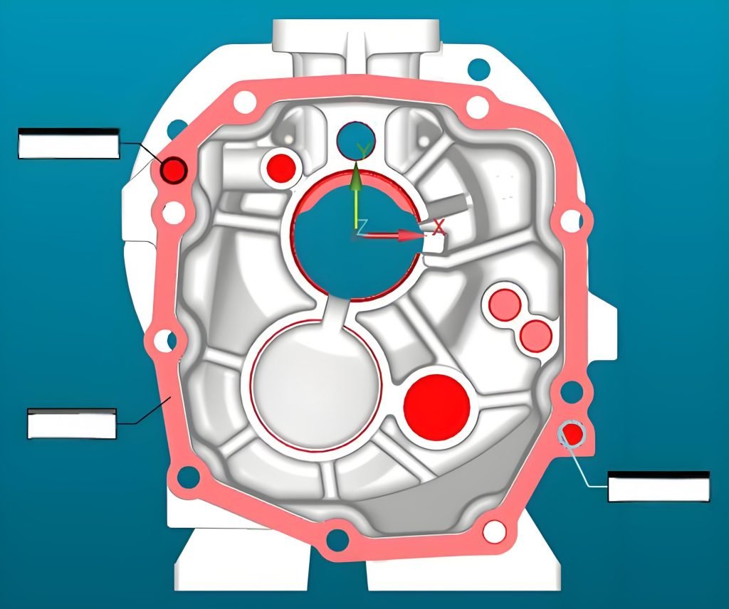
When machining engine blocks, manufacturers often select the bottom of the block as the primary datum. The centerlines of the cylinders become secondary datums. This datum reference frame ensures accurate alignment of boreholes and surfaces. Modern CNC machining centers use this datum reference frame to set up and machine engine blocks, translating theoretical GD&T concepts into practical manufacturing operations.
The use of datums in engine block machining controls critical relationships between features like cylinder bore spacing and crankshaft bore alignment. Datum-referenced tolerances ensure that engine components from different suppliers will properly assemble and function together in the final engine. By establishing a precise coordinate system, manufacturers can produce high-quality parts with precise geometric control.
Conclusion
Datums are the backbone of precision engineering, providing a reference frame for measurements and geometric controls. In GD&T, datums establish a coordinate system that guides the manufacturing process, ensuring proper part fit and function. The hierarchy of primary, secondary, and tertiary datums constrains all six degrees of freedom, creating a complete datum reference frame. Proper datum selection is critical, impacting the entire manufacturing and inspection process. By understanding datums, engineers can improve design and manufacturing efficiency, quality control, and product performance.


