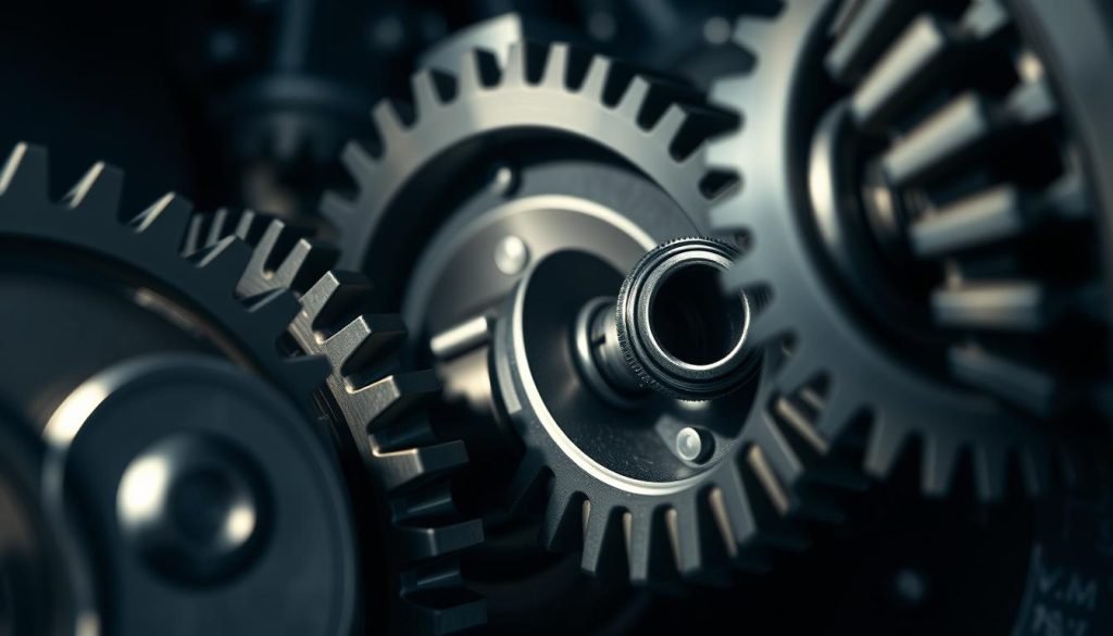
More than 90% of modern machines use at least one gear to move power in a controlled way — a quick fact that shows how central these parts are to industry and daily life.
A gear is a round, toothed wheel that meshes with a mate to transfer motion and torque without slip. This simple action changes speed, direction, and force inside a transmission or reducer.
Understanding different gear types helps you pick the right solution for your application, whether you need quiet service in an automotive differential or compact power delivery in a robot. You’ll learn how shaft layout—parallel, intersecting, or non-parallel—narrows viable choices and affects packaging.
We’ll also touch on common tooth profiles like the involute, and practical selection criteria such as material, surface finish, and manufacturing. Read on to get a clear roadmap for widely used designs and how they impact uptime, cost, and performance for your projects.
What Is a Gear?
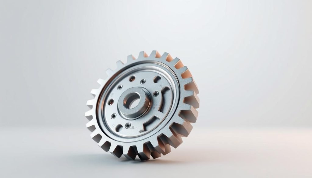
A gear is a precision wheel with teeth that mesh to move power cleanly between rotating parts. It transfers torque and motion with no slip, so you get predictable performance in tight spaces.
Teeth are spaced evenly and follow a defined profile—most often the involute shape—to keep engagement smooth and the velocity ratio constant. That tooth geometry minimizes shock and wear during duty cycles.
In practice, gears used in machinery can increase speed, multiply torque, or reverse direction rotation by pairing different sizes. Two or more in sequence form a gear train that tailors output speed and torque to your need.
How Does a Gear Work
Gears work by converting input rotation into controlled output through engaged teeth. When a driving gear turns, the driven gear follows because the teeth mesh and transfer force at the contact point.
A small pinion driving a larger gear raises torque while cutting speed. Swap sizes and you trade torque for speed. Two external gears of equal pitch reverse direction rotation, but an external meshing with an internal gear keeps the same rotation sense.
Circular involute teeth keep the gear ratio constant, so speed and motion torque remain steady for precision transmission. Proper center distance and aligned shafts are essential to keep teeth loading even and reduce noise and wear.
In gear trains, compounded ratios multiply, letting you get high reduction or high speed in compact layouts. Non-circular gears serve variable motion needs, though most industrial drives use circular gears for predictable power and life.
Lubrication separates tooth surfaces, lowers friction and heat at the mesh, and directly improves efficiency and service life.
Types of Gears
Below you’ll find a compact guide to the most used gear families and practical notes on where they fit. Use this to match a selection to your application, balancing cost, packaging, and efficient power delivery.
Spur and pinion
Spur gears are simple, cheap, and widely used on parallel shafts. They give efficient power transfer but get noisy at high speed.
A small spur gear or pinion gears pair is ideal where cost and simplicity matter most.
Helical gears
Helical gears run quieter and carry higher loads than spur types. Their helical teeth let engagement start gradually for smoother action.
Expect axial thrust; plan bearings accordingly for continuous-duty drives and high-speed applications.
Bevel families
Bevel gears handle intersecting shafts. Straight bevel suits lower speed; spiral bevel gears take higher load with less noise.
Zerol bevel gives spiral benefits with zero lead angle for simpler thrust handling in some layouts.
Worm drives
Worm gears deliver very high single-stage reduction and can be self-locking. They need careful lubrication and material pairing due to sliding contact.
Rack and pinion
Rack pinion systems convert rotary motion into linear travel. Use them for steering and precise positioning axes.
Planetary and internal
Internal gears and planetary systems pack high ratios into compact, coaxial layouts. They work where space and torque density matter.
Herringbone and screw
Herringbone (double helical) cancels axial thrust for heavy-duty, smooth service. Crossed helical or screw gears suit skew shafts in tight spaces.clearance or space, hypoid delivers compact, high-torque solutions for automotive and industrial applications.
Commonly Used Gear Materials
Your material choice controls tooth strength, heat handling, and maintenance needs. Match material to load, environment, and budget to get the best life from a transmission or drive you buy.
Alloy steels, cast iron, and bronze for heavy loads
Alloy steels dominate where high torque and shock occur. They take heat treatment for hard, fatigue-resistant teeth you need in heavy machinery and industrial machinery.
Cast iron and bronze give damping and galling resistance. Use them when machinability, cost, or corrosion behavior matters.
Engineering plastics and self-lubricating polymers
Plastics cut weight and resist corrosion. They lower noise and often run without grease for moderate duty or continuous applications.
In worm or screw meshes, pair a hardened steel worm with a bronze or polymer wheel to reduce wear at sliding contacts.
Surface treatments and finishing
Carburizing and nitriding harden the case while keeping a tough core for impact resistance. Grinding and lapping refine profiles to tight tolerances and lower noise.
Manufacturing Techniques for Gears
The way you make a gear decides its accuracy, cost, and readiness for volume runs.
Cutting methods
Hobbing efficiently produces spur gears and helical gears with repeatable tooth forms across many batches. It suits external teeth on shafts and gives low unit cost at scale.
Shaping handles internal teeth and features a hob cannot reach. Broaching is ideal when you need fast cycle times for internal splines and high-volume parts once tooling is justified.
Finishing for precision
Grinding, lapping, and honing refine profile and micro-geometry. These finishes lower noise, raise efficiency at running speed, and improve load sharing across teeth.
Forming and additive
Forging and powder metallurgy make near-net blanks that cut machining time and material waste for heavy-duty parts. 3D printing lets you prototype custom tooth shapes, lubrication channels, and polymer samples before hard tooling.
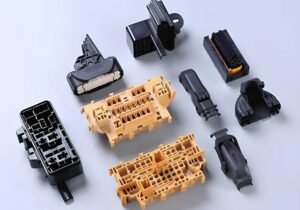
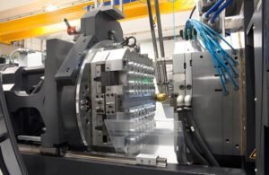
Injection molding and CNC
Injection molding scales polymer gears for high-volume programs with consistent quality and low unit cost. CNC machining bridges prototype to low-volume metal runs and supports custom ratios and quick turns.
Design and Performance Factors That Affect Gear Systems
Engineering reliable, quiet gear systems means you must balance contact, lubrication, and support. Small choices in tooth form and housing stiffness change noise, efficiency, and service life.
Contact ratio, efficiency, backlash, and noise
Contact ratio controls how many teeth share load as gears mesh. A higher contact ratio smooths torque delivery and cuts noise at speed.
Rolling-dominant meshes give higher efficiency than sliding-heavy pairs. Worm drives trade efficiency for compact reduction and need special care.
Backlash lets lubricant flow and allows thermal growth, but keep it tight for servo accuracy. Noise comes from profile errors, misalignment, and variable mesh stiffness.
Lubrication strategy for sliding vs rolling contact
Match lubricant to contact type: EP oils suit sliding contacts; lower-viscosity oils cut churning losses in high-speed rolling meshes.
Lubricant film depends on load, speed, and viscosity. Surface finishing like grinding or lapping helps maintain a stable film and lower friction.
Considerations When Choosing Gears
Begin with performance targets—torque peaks, continuous speed, and expected runtime—to narrow options fast. Those application requirements shape material, tooth profile, and finish choices for reliable service in your environment.
Match the layout and load
Decide whether your shafts are parallel, intersecting, or skewed. That choice cuts the candidate families of gears quickly and limits packaging and bearing needs.
Check space, fit, and standards
Confirm center distance, module or DP, and the allowable envelope so parts mesh without interference. Use AGMA guidance for tolerances and pick manufacturing methods that meet those specs.
Buyer’s checklist to converge on a short list
Start with these practical checks: required torque and speed, duty cycle, and environment (temperature, humidity, contamination). Next, pick shaft arrangement, verify center distance and tooth thickness, and set noise and backlash limits. Compare lifecycle cost, lubrication strategy, and maintenance access. Finally, choose between off-the-shelf ratios or a custom cut and align material plus heat treatment to corrosion and cleanliness needs.
Applications by Industry in the United States
Industry needs in the U.S. drive which gear families get specified for a job—quiet, compact, or heavy-duty. Match the right solution to your application to save space, cut noise, and meet load demands for reliable power transmission.
Automotive
Automotive drivelines favor hypoid and spiral bevel gears in differentials for quieter, high-torque right-angle power transmission. Transmissions use helical gears and planetary sets for high speeds and compact packaging.
Steering systems rely on rack pinion layouts for direct linear response with tight backlash control.
Aerospace and robotics
Aerospace actuators and gearboxes choose finely ground spur and helical gears to run at high speeds with precise positioning. Robotics often use low-backlash helical and bevel gears for repeatable motion in tight joints.
Industrial machinery and conveyor systems
Industrial machinery and conveyor systems commonly use spur for simplicity and helical for quiet continuous duty. Worm gears appear where single-stage reduction and holding ability matter, such as indexing drives in packaging and printing lines.
Process equipment may adopt double helical for heavy loads with no net thrust. Material choices vary: polymers in food handling, carburized steels in heavy reducers.
Maintenance and Reliability: Getting the Most from Your Gear Systems
Regular checks and targeted upkeep prevent small tooth wear from becoming a costly failure. You should set a steady inspection cadence to spot wear patterns on teeth and correct contact early.
Keep lubricants fresh and at proper viscosity. Contamination and heat drive most premature failures, so replace oil when it shows contamination or viscosity loss.
Monitor backlash and noise trends daily or weekly depending on duty. Rising noise often signals bearing wear, misalignment, or damaged teeth in the transmission.
Worm drives need specified EP lubricants and checks for thermal buildup under sustained load. Verify thrust bearings in helical and spiral bevel assemblies to prevent edge loading and pitting.
Inspect seals and breathers, control cleanliness, and watch operating temperature. Train your techs on contact marking and torque procedures. Plan spares and interchangeability to cut downtime across applications.
Fecision-Gear Machining Services
Fecision brings engineering-grade gear machining and complete production services under one roof. You get support from early design reviews through metrology and delivery.
Custom cutting, grinding, and precision finishing
We cut precision gears and pinion gears using hobbing and shaping, then finish by grinding and lapping for quiet, efficient power. That workflow reduces noise and improves contact life in your assemblies.
Material selection and application engineering
Our engineers guide material and heat-treatment choices across alloy steel, bronze, and self-lubricating polymers. You get recommendations that match duty cycle, environment, and expected life for your applications.
Prototyping to production: CNC, molding, and 3D printing
Rapid prototypes via CNC and 3D printing prove ratios and geometry before tooling. For volume polymer parts, injection molding delivers repeatability and lower unit cost.
From single spares to multi-thousand pieces, Fecision designs for manufacturability, runs full metrology and contact-pattern checks, and supports re-engineering legacy sets to improve life or noise without a full gearbox redesign.
Conclusion
Good gear selection begins when you translate application needs into measurable specifications. Start by matching axis layout, ratio, and duty to the right gear family so your parts run as intended.
For high speed and quiet drives, favor helical and bevel variants; choose worm wheels for compact high reductions and rack‑and‑pinion for linear motion. These choices affect torque and speed outcomes directly.
When you’re ready, Fecision turns your specs or CAD into finished parts. Share your files today to accelerate prototyping, validation, and production with engineering, machining, and finishing under one roof.