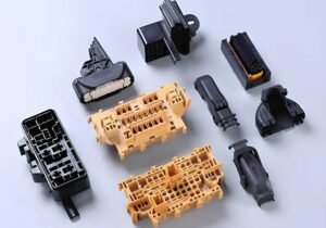
Did you know that imprecise part design can lead to significant manufacturing costs? In today’s fast-paced engineering landscape, precise communication between design and production teams is crucial. Geometric Dimensioning and Tolerancing (GD&T) is a sophisticated system that defines and communicates engineering tolerances through a symbolic language on technical drawings and 3D models.
By understanding GD&T, you’ll be able to create more manufacturable designs, reduce production costs, and ensure parts function as intended. This is achieved by specifying the allowable variation in part features and assemblies
As you explore GD&T, you’ll discover its importance in modern engineering practices and how it can benefit your projects.
Understanding Geometric Dimensioning and Tolerancing (GD&T)
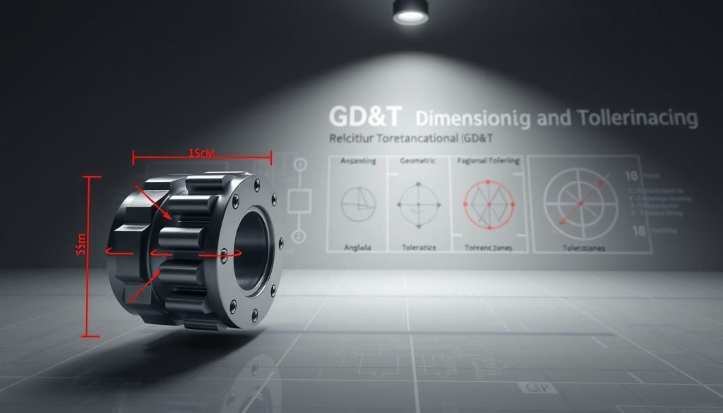
As you delve into the realm of engineering, understanding GD&T becomes crucial for defining and communicating dimensions and tolerances. Geometric Dimensioning and Tolerancing is a system that uses a symbolic language to describe the nominal geometry of parts and assemblies, specifying the degree of accuracy and precision needed for each controlled feature.
What is GD&T?
GD&T is a universal engineering language that uses symbols and annotations to define the allowable variation in manufactured parts. Unlike traditional coordinate dimensioning, GD&T focuses on the functional requirements of parts rather than just their physical dimensions, allowing for more precise control of critical features.
By using GD&T, engineers can communicate design intent unambiguously between designers, manufacturers, and quality control personnel, ensuring everyone interprets drawings the same way.
The History and Development of GD&T
The development of GD&T dates back to the early 1940s when Stanley Parker realized that parts meeting functional requirements were being rejected due to out-of-tolerance measurements. He pioneered tolerancing practices that addressed the functional needs of parts, publishing the first work on GD&T in 1940.
Understanding the historical development of GD&T helps engineers appreciate why certain conventions and rules exist within the system.
Dimensional Tolerance vs. Geometric Tolerance
The distinction between dimensional tolerance, which controls only size, and geometric tolerance, which controls form, orientation, location, and runout, is fundamental to understanding how GD&T improves manufacturing efficiency.
By specifying tolerances based on function rather than arbitrary measurements, GD&T allows for greater flexibility in manufacturing while maintaining the integrity of the design intent.
The Importance of GD&T in Manufacturing
In today’s manufacturing landscape, the significance of Geometric Dimensioning and Tolerancing (GD&T) cannot be overstated. As you navigate the complexities of modern production, understanding GD&T’s role is crucial for ensuring the quality and functionality of manufactured parts.
Why GD&T Matters in Modern Engineering
GD&T matters because it allows designers to communicate the design intent clearly, focusing on the function of the part rather than just its dimensions. By doing so, it enables the loosening of less critical tolerances, making parts easier and cheaper to produce. For instance, in the design of a mirror, traditional dimensioning might not capture the surface’s form accurately, potentially leading to a wavy surface that fails to function as intended. GD&T’s focus on form control ensures that the surface meets the required specifications.
In today’s manufacturing environment, where precision, consistency, and interchangeability are critical, GD&T has become increasingly important. It provides a framework for consistent inspection methods, reducing disagreements between suppliers and customers about whether parts meet specifications.
Benefits of Implementing GD&T
By implementing GD&T, companies can significantly reduce manufacturing costs by specifying appropriate tolerances based on functional requirements. This approach ensures that critical features receive tight tolerances while non-critical features have more relaxed specifications. As a result, companies typically see improvements in assembly fit, reduced scrap rates, and fewer engineering change orders during production. Moreover, GD&T facilitates better communication between design and manufacturing teams, helping to identify potential manufacturing issues earlier in the product development cycle.
How GD&T Works
GD&T is a systematic approach to controlling part variation through a set of rules and symbols that ensure precise communication of design intent across all stages of manufacturing. By understanding and applying GD&T principles, manufacturers can ensure that parts are produced within specified tolerances, thereby maintaining the functional integrity of the final product.
The SLOF Concept: Size, Location, Orientation, and Form
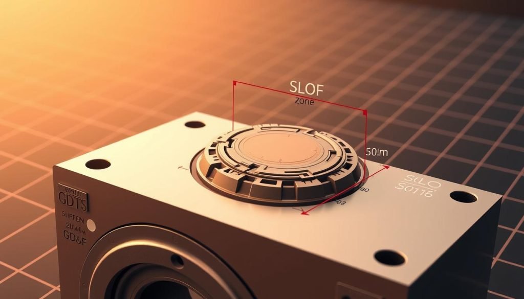
The SLOF concept is fundamental to GD&T, encompassing four critical aspects of a feature: size, location, orientation, and form. Size refers to the physical dimensions of a feature, while location pertains to its position relative to other features in 3D space. Orientation involves the angular relationship between features, and form refers to the overall shape or geometry of a feature.
Fundamental Rules of GD&T
GD&T is governed by a set of fundamental rules that ensure consistent interpretation and application. One key principle is Rule #1, which states that the form of an individual feature is controlled by its size limits. Additionally, the envelope principle requires that the feature’s surface not exceed a perfect geometric form at its maximum material size.
| Rule | Description |
| Rule #1 | Form control of individual features |
| Envelope Principle | Feature surface not exceeding perfect geometric form at maximum material size |
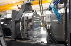
GD&T in the Manufacturing Process
In the manufacturing process, GD&T plays a crucial role in guiding everything from tooling design to inspection methods. By specifying datums and tolerance zones, GD&T ensures that parts are produced and inspected according to the design intent, thereby maintaining the functional requirements of the final product.
Understanding how tolerance zones work in three dimensions is crucial for properly implementing and interpreting GD&T specifications. Tolerance zones define the allowable space within which a feature must lie, and they are often more generous than traditional plus/minus tolerancing while still ensuring functionality.
Essential GD&T Concepts and Components
To effectively apply GD&T, you need to understand its essential concepts and components. These elements work together to ensure that parts are manufactured to precise specifications, meeting their intended functional requirements. In this section, we’ll explore the fundamental concepts that underpin GD&T, including basic dimensions, feature control frames, datums, material condition modifiers, and tolerance zones.
Basic Dimensions and Their Role
Basic dimensions are theoretically exact values used as a reference for geometric tolerances. They are shown in rectangular frames and are not directly toleranced themselves. Instead, they serve as the basis for calculating the tolerance zones within which features must lie. Understanding basic dimensions is crucial for accurately interpreting GD&T specifications.
Feature Control Frames Explained
A feature control frame is a standardized rectangular box that contains all the information needed to define a geometric tolerance. It includes the GD&T symbol, tolerance value, modifiers, and datum references. Feature control frames provide a concise and unambiguous way to communicate complex tolerance information, ensuring that parts are manufactured correctly.
Datums and Datum References
Datums are theoretically perfect geometric references from which measurements are made. Datum features are the actual physical features on a part that establish these references. The datum reference frame establishes the coordinate system for the part, determining how it will be oriented during manufacturing and inspection. Proper selection of datum features is critical to ensuring that the part functions as intended in its final assembly.
Material Condition Modifiers (MMC, LMC, RFS)
Material condition modifiers allow for additional tolerance when features vary from their worst-case size. Maximum Material Condition (MMC) applies when a feature contains the maximum amount of material, allowing for “bonus tolerance” as the feature departs from this condition. Least Material Condition (LMC) is used less frequently but is valuable for controlling minimum wall thickness between features. Regardless of Feature Size (RFS) applies regardless of the feature’s size, ensuring that the tolerance is always maintained.
| Modifier | Description | Application |
| MMC | Maximum Material Condition | Allows bonus tolerance as feature size departs from MMC |
| LMC | Least Material Condition | Controls minimum wall thickness between features |
| RFS | Regardless of Feature Size | Applies tolerance regardless of feature size |
Tolerance Zones
Tolerance zones define the three-dimensional space within which a feature or element must lie to conform to specifications. Understanding tolerance zones is essential for ensuring that parts meet their functional requirements. By defining the acceptable limits of variation, tolerance zones help manufacturers produce parts that are accurate and reliable.
By grasping these essential GD&T concepts and components, you can ensure that your parts are manufactured to precise specifications, meeting their intended functional requirements and performing as expected in their final assembly.
Common GD&T Symbols and Their Applications
GD&T symbols provide a common language for engineers to describe the allowable variation in the geometry of a part. These symbols are categorized into five main groups, each addressing different aspects of geometric variation.
Form Controls
Form controls define the shape of individual features without reference to other features. They include flatness, straightness, circularity, and cylindricity. For instance, flatness is the condition of a surface having all elements in one plane, symbolized by a parallelogram. Straightness is a condition where an element of a surface is a straight line.
Orientation Controls
Orientation controls define the angular relationship between features and datum references. They include perpendicularity, parallelism, and angularity. These controls ensure proper alignment in assemblies.
Location Controls
Location controls define where features should be located relative to datum references or other features. They include position, concentricity, and symmetry. These are critical for ensuring proper fit and function.
Profile Controls
Profile controls are versatile symbols that can control form, orientation, and location simultaneously. They include profile of a line and profile of a surface, making them powerful tools for complex surfaces.
Runout Controls
Runout controls are specialized controls for rotating parts that limit the variation when a part is rotated around a datum axis. They include circular runout and total runout.
Understanding when to apply each GD&T symbol is as important as knowing what the symbol means. The selection of the appropriate control depends on the functional requirements of the part. Engineers can reference GD&T symbol charts during the design process to ensure accurate specification.
Conclusion: Implementing GD&T in Your Engineering Practices
The successful integration of GD&T into your design process can significantly improve product quality and reduce manufacturing costs. To achieve this, implementing GD&T in your engineering practices requires a systematic approach, starting with proper training for all team members involved in the design and manufacturing process.
Begin by identifying the critical functional requirements of your parts and assemblies, then select the appropriate GD&T symbols and tolerances to control those requirements. This ensures that everyone involved in technical drawings speaks the same language, reducing misunderstandings and guesswork.
By adopting GD&T, you can allow wider tolerances on non-critical features while maintaining tight control where it matters, ultimately enhancing product quality and reducing scrap rates. As designs become more complex, the clear communication provided by GD&T becomes increasingly important to engineering success.
FAQ
What is the purpose of a feature control frame in GD&T?
A feature control frame is used to specify the tolerance zone for a particular feature, providing a clear and concise way to communicate the allowable variation in the feature’s size, location, orientation, or form.
How do datums and datum references work in GD&T?
Datums are reference points, axes, or planes that serve as a basis for locating and orienting features on a part. Datum references are used to establish the relationship between the datum and the feature being controlled, ensuring that the feature is properly positioned and oriented.
What is the difference between maximum material condition (MMC) and least material condition (LMC)?
MMC refers to the condition where a feature contains the maximum amount of material, while LMC refers to the condition where a feature contains the minimum amount of material. These modifiers are used to specify the tolerance zone for a feature based on its material condition.
How do you determine the tolerance zone for a profile control?
The tolerance zone for a profile control is defined by two boundaries, one inside and one outside the ideal profile. The feature must lie within this zone to meet the specified tolerance.
What is the significance of straightness in form controls?
Straightness is a form control that ensures a feature is straight within a specified tolerance. It is used to control the deviation of a feature from a perfect straight line.
How does GD&T impact the inspection process?
GD&T provides a clear and unambiguous language for specifying tolerances, making it easier to inspect parts and determine whether they meet the required specifications. This helps to reduce errors and improve the overall quality of the parts.