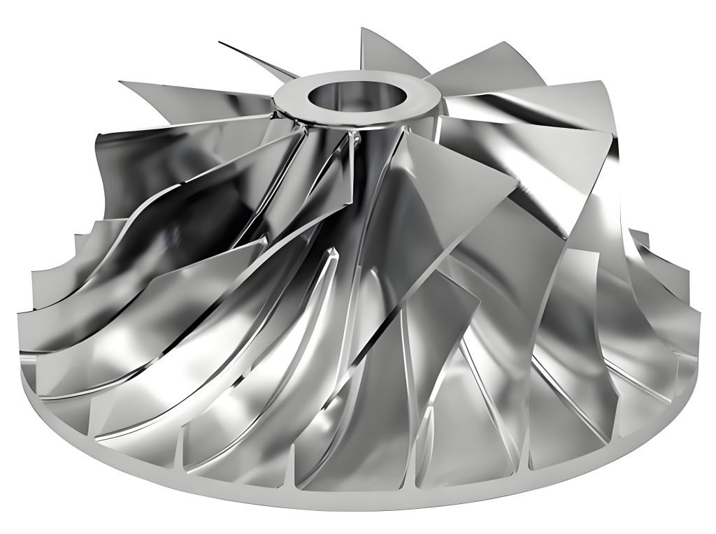
An impeller is the rotating part of fluid moving equipment like pumps, compressors and mixers that transfers energy from the motor to the fluid. It achieves this by accelerating the fluid outwards from the centre of rotation, increasing pressure and flow.
In industrial operations, impellers move liquids and gases through pipelines and processing systems. With different performance requirements across industries, different types of impeller designs are made for specific tasks. This article will cover the main types of industrial impeller designs, their categories and how to choose the right one for your application.
What Is an Impeller?
An impeller is the heart of fluid moving equipment. It’s a driven rotor that accelerates fluid, transfers energy and increases pressure. This specialized component converts the mechanical energy from a motor into kinetic energy in the fluid. At its core an impeller is a short cylinder with an open inlet (called an “eye”), vanes to push fluid radially and a bore that accepts a drive shaft.
Components and Working Principle
The working principle of impellers follows specific principles of fluid dynamics. As the motor activates the shaft it rotates the impeller at speeds ranging from 500 to 5,000 rpm. This rotation creates a low pressure area at the center that draws fluid in. Then the centrifugal force generated by the curved vanes pushes the fluid out, where the expanding volute channel converts this kinetic energy into pressure energy, ensuring constant flow through the system.
A typical impeller consists of:
- Blades or vanes: Curved or straight surfaces that direct fluid flow.
- Hub or shaft: The central part connected to the motor.
- Shroud (in some designs): Covers that enclose the impeller blades for specific flow characteristics.
When the impeller spins centrifugal or axial forces push the fluid through the system. This motion converts mechanical energy into kinetic energy and pressure which is then harnessed for pumping, mixing or compression.
Common Applications
In centrifugal pumps impellers accelerate fluid outward from the center of rotation. This spinning motion turns mechanical energy into speed and pressure, helping move water efficiently in systems like water supply and irrigation. Impellers also play a vital role in water jets powering high speed boats, compressors, agitated tanks for mixing fluids, blast furnaces and superchargers for internal combustion engines.
Motorized impellers, also called backward curved impellers, are great for situations where strong airflow is needed in a small space. These components maximize heat dissipation, extend the life of electronic components. Their pressure performance is ideal for HVAC systems, networking equipment and electronic cabinet cooling.
Importance in various industries
Impellers are critical components across many industries. In water treatment plants free flow impellers handle wastewater containing complex mixtures of fibers, solids and entrapped gasses. For the chemical industry impellers are made of stainless steel or bronze with a specific number of blades to direct fluid flow.
Also impellers support industrial and commercial applications by moving and pressurizing fluids. Their design and performance is crucial for applications from manufacturing processes to marine propulsion systems. In food processing sine wave impellers gently transfer damage prone products without breakage.
Overall impellers are indispensable across sectors that require reliable fluid movement, pressure generation or mixing capabilities.
Classification of Impellers: How Many Types of Impellers Are There?
Impellers are the rotating parts of pumps and mixers that help move fluids. They are available in various types, each designed for a specific use. Engineers and manufacturers classify impellers based on how they move fluid, their shape and how they’re used.
1. Based on Fluid Flow Direction
This classification is based on the way fluid flows through the impeller.
- Radial Flow Impeller: Pushes fluid outwards at a 90-degree angle from the shaft. It’s great for high-pressure, low-flow applications.
- Axial Flow Impeller: Moves fluid straight along the shaft (up or down). It’s ideal for moving large volumes of fluid with low pressure.
- Mixed Flow Impeller: It combines both radial and axial flow, directing the fluid at an angle. It balances pressure and flow for medium-duty tasks.
2. Based on Mechanical Design
This classification looks at the shape and structure of the impeller:
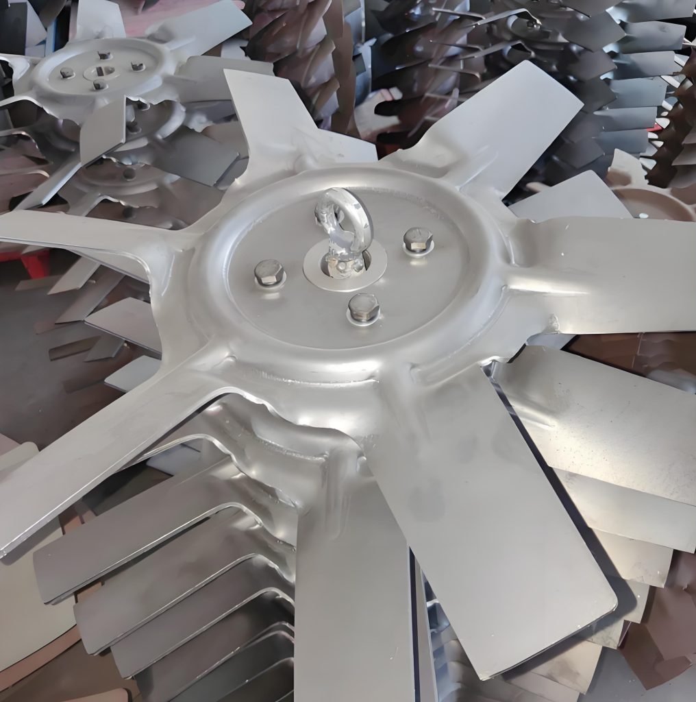
- Open Impeller: Has blades attached to a central hub with no side walls. It’s easy to clean and good for handling solids or slurries.
- Semi-Open Impeller: Has a back wall but no front wall. It’s a good middle-ground option for moderate solids and easy maintenance.
- Closed Impeller: Has both front and back walls enclosing the blades. It’s efficient and used for clean liquids with high pressure.
3. Based on Application Type
This grouping is based on the job the impeller is meant to do:
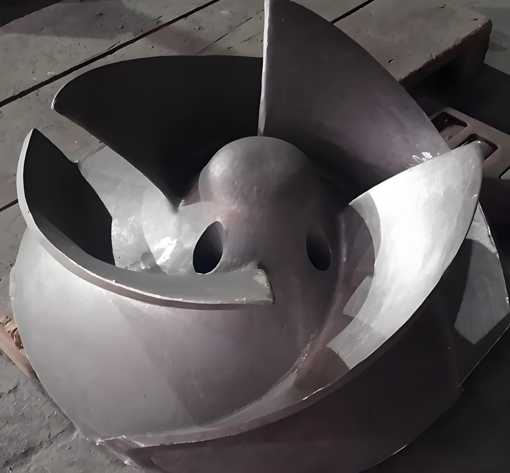
- Vortex Impellers: Create a swirling motion to move fluids gently. Best for handling solids without clogging.
- Channel Impellers: Have large flow paths and are used for liquids with some solids. They provide a strong, steady flow.
- Multi-stage Impellers: Several impellers are stacked in one system to create very high pressure. Used in deep wells or high-lift systems.
Each impeller type is designed to match specific requirements for pressure, flow rate, and the type of fluid being moved. Choosing the right type ensures better performance and longer equipment life.
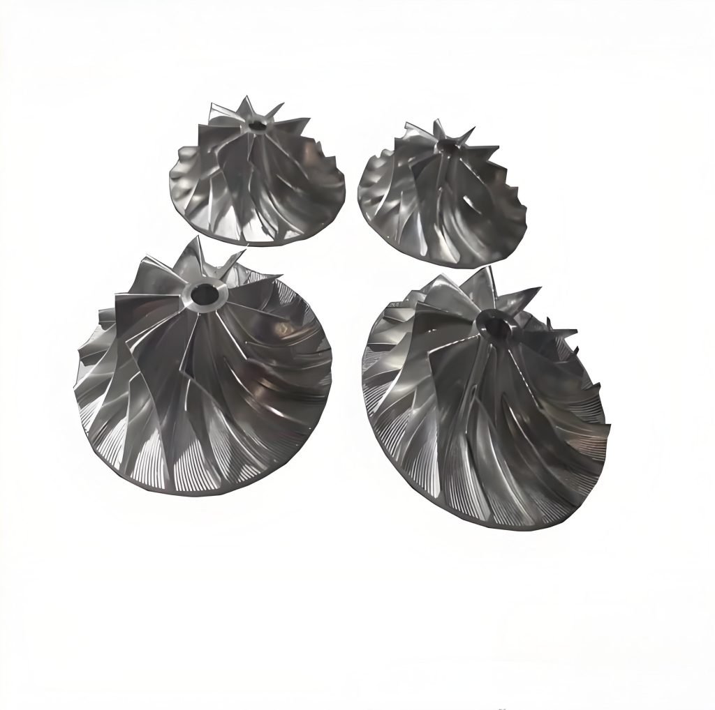
Major Types of Impeller
Industrial pump performance relies heavily on the specific impeller design. Each major type serves distinct purposes across various applications, with selection depending on operational requirements.
Radial Flow Impeller
Radial flow impellers push fluid outward at a right angle to the shaft, resulting in high pressure and moderate flow rates. They mainly create sideways fluid movement, which leads to strong shear forces. Radial impellers feature flat characteristic curves that remain relatively constant regardless of flow changes, with typically only 3% head rise or less. Essentially, these designs excel in applications requiring high pressure generation, making them suitable for industrial processing and chemical applications.
Ideal For:
- High-pressure, low-flow applications
- Processes requiring consistent pressure over long distances
Common Uses:
- Centrifugal pumps for chemical dosing
- Boiler feed systems
- High-pressure water jetting systems
Axial Flow Impeller
Axial flow impellers function like propellers in a pipe, moving fluid parallel to the shaft axis. Unlike radial designs, these impellers have no centrifugal component in their discharge. Their blades typically make angles less than 90° to the rotation plane, creating strong vertical currents. Notably, axial impellers handle up to three times more water at lifts under 4 meters compared to centrifugal pumps. Their power requirements increase as flow decreases, opposite to centrifugal pump behavior.
Ideal For:
- Low-pressure, high-flow applications
- Circulation and mixing in large tanks
Common Uses:
- Cooling water circulation in power plants
- Irrigation pumps
- Aeration tanks in wastewater treatment
Mixed Flow Impeller
Mixed flow impellers bridge the gap between radial and axial designs. Their diagonal operation provides both centrifugal force and axial pushing action, creating a dual pumping effect. These versatile components deliver both high flow rates and substantial discharge pressure. For applications requiring heads up to 60 m, mixed flow impellers operate effectively, though circumferential velocity must remain between 25-30 m/s to prevent cavitation.
Ideal For:
- Medium-flow, medium-pressure applications
- Processes that need a balance between pressure and flow
Common Uses:
- Municipal water supply systems
- Flood control pumps
- Marine propulsion systems
Open Impeller
Open impellers feature vanes attached directly to a central hub without shrouds. Their exposed structure makes them ideal for handling suspended solids and simplifies cleaning procedures. Additionally, they run at higher tip speeds than closed impellers, generating more head per stage (15,000–25,000 ft-lbs/lb). Primary applications include water treatment, paper stock processing, and small pumps handling solid-laden fluids.
Features:
- Simple construction
- Easy to clean and maintain
- Less efficient compared to closed designs
Best For:
- Wastewater pumping
- Chemical slurry movement
- Pulp and paper industry
Semi-Open Impeller
Semi-open impellers incorporate a single shroud mounted on either the front or back. This design presents a practical compromise between open and closed configurations. They efficiently handle liquids containing moderate amounts of suspended solids without easily clogging. Nevertheless, they create considerable axial thrust, often requiring thrust bearings for proper operation.
Features:
- Improved efficiency over open impellers
- Moderate ability to handle solids
- Adjustable wear plates to maintain performance
Best For:
- Light to moderately contaminated liquids
- Medium-viscosity fluids
- Applications needing better flow stability
Closed Impeller
Closed impellers feature protective shrouds on both sides of the vanes. This configuration maximizes hydraulic efficiency (85-92%) compared to semi-open designs (75-85%). Primarily used with clean, non-viscous fluids, closed impellers excel in high-pressure applications and offer longer wear life. For this reason, they dominate in chemical processing, HVAC systems, and boiler feed pumps.
Features:
- High hydraulic efficiency
- Not suitable for handling solids
- Requires precise alignment and minimal wear
Best For:
- Clean water and chemical solutions
- High-speed applications in process plants
- HVAC systems and pressure boosting
Comparison Table of Impeller Types
| Impeller Type | Flow Direction | Efficiency | Solids Handling | Ideal Application |
| Radial Flow | Perpendicular | High | Low | High-pressure pumps |
| Axial Flow | Parallel | Medium | Low | Cooling & circulation |
| Mixed Flow | Angled | Medium-High | Medium | Irrigation, flood control |
| Open Impeller | Varies | Low | High | Viscous fluids, food |
| Semi-Open Impeller | Varies | Medium | Moderate | Chemical processes |
| Closed Impeller | Varies | High | Low | Clean water, pharm |
Choosing the Right Industrial Impeller
Choosing the right industrial impeller requires careful consideration of multiple operational factors. Beyond understanding the different types, engineers must evaluate specific application requirements to maximize efficiency and performance.
1. Viscosity of the Material
One key factor to consider is the fluid’s thickness, known as its viscosity. Thin liquids work well with fast and efficient hydrofoil impellers. Thick materials need stronger impellers, like axial flow or turbine blades, that can handle more resistance.
2. Power Input and Torque
Power is required to spin the impeller. As the impeller gets bigger the power required increases a lot. If this isn’t calculated correctly, it can damage the equipment. It’s especially important to get this right when increasing the size of the system.
3. Tank Dimensions and Configuration
The shape and size of the tank affects how well the impeller works. A tank that’s about as tall as it is wide usually gives the best results. Bigger tanks often need more than one impeller to mix everything properly. Whether the tank stands up (vertical) or lies down (horizontal) also affects the design.
4. Material Compatibility
The impeller must be made of the right material for the job. Stainless steel is strong and resistant to rust, it’s a good all-around choice. Bronze works well with salty liquids and cast iron is good for alkali substances but can be damaged by acids.
5. Component Fit and Compatibility
Before selecting an impeller, ensure all components are compatible and fit together correctly. The impeller should fit the shaft and the shaft should fit the stirrer. If the parts don’t match the system won’t work well and may need repairs.
6. Cost-Effectiveness
Lastly the cost-benefit ratio must be considered. The goal is to strike a balance between quality, efficiency and long term maintenance costs. Investing in a high quality, durable impeller often results in greater savings over time than choosing a cheaper, less reliable alternative.
Conclusion
Impellers are at the heart of many industrial systems, pumping water and chemicals, compressing gases and mixing ingredients. It is essential to understand the various types of impellers such as axial, mixed flow, radial, open, semi-open, and closed, for engineers and plant operators.
Each impeller type serves a specific purpose based on flow characteristics, pressure demands and fluid properties. The right choice depends on careful evaluation of operational needs and system specifications. For best results consult with industrial pump or impeller experts when selecting components. Their expertise will ensure your equipment performs at maximum with minimum operational risk.