When designing a part, have you ever wondered how to optimize its corners for both aesthetics and functionality? The choice between rounded corners and angled edges can significantly impact the structural integrity and manufacturing complexity of your design.
Fillets and chamfers are two common edge treatments used in engineering and manufacturing. While they both eliminate sharp edges, they serve different purposes and offer distinct benefits.
Understanding the difference between these features is crucial for making informed decisions about your part design. The right choice can enhance not only the appearance but also the overall performance and cost of your components.
Understanding Edge Treatments in Design and Manufacturing
The Importance of Edge Modifications
Edge modifications are critical for multiple reasons. Primarily, they enhance safety by eliminating sharp edges that could cause injury during handling or assembly. Properly designed edge treatments also significantly reduce stress concentration at corners and intersections, thereby preventing premature part failure under load. This is crucial for ensuring the durability and reliability of machined parts.
Impact on Product Performance and Aesthetics
Edge treatments not only affect the mechanical properties of parts but also their visual appeal and perceived quality. The choice between different edge treatments must consider both the technical requirements of the component and the aesthetic expectations of the end product. By understanding the relationship between edge design and part performance, engineers can make informed decisions that balance functional requirements with manufacturing constraints.
What is a Fillet?
A fillet is essentially a rounded interior or exterior corner that creates a smooth transition between two surfaces, replacing what would otherwise be a sharp intersection.
Definition and Characteristics
A fillet is characterized by its curved surface that blends two surfaces together. This curvature helps in distributing mechanical stress across the surface rather than concentrating it at a single point, thereby significantly improving part durability. The radius size of a fillet directly affects its stress-reduction capabilities and the complexity of manufacturing the feature.
Types of Fillets
Fillets can be categorized into two primary types based on their application: interior (concave) fillets and exterior (convex) fillets.
Interior (Concave) Fillets
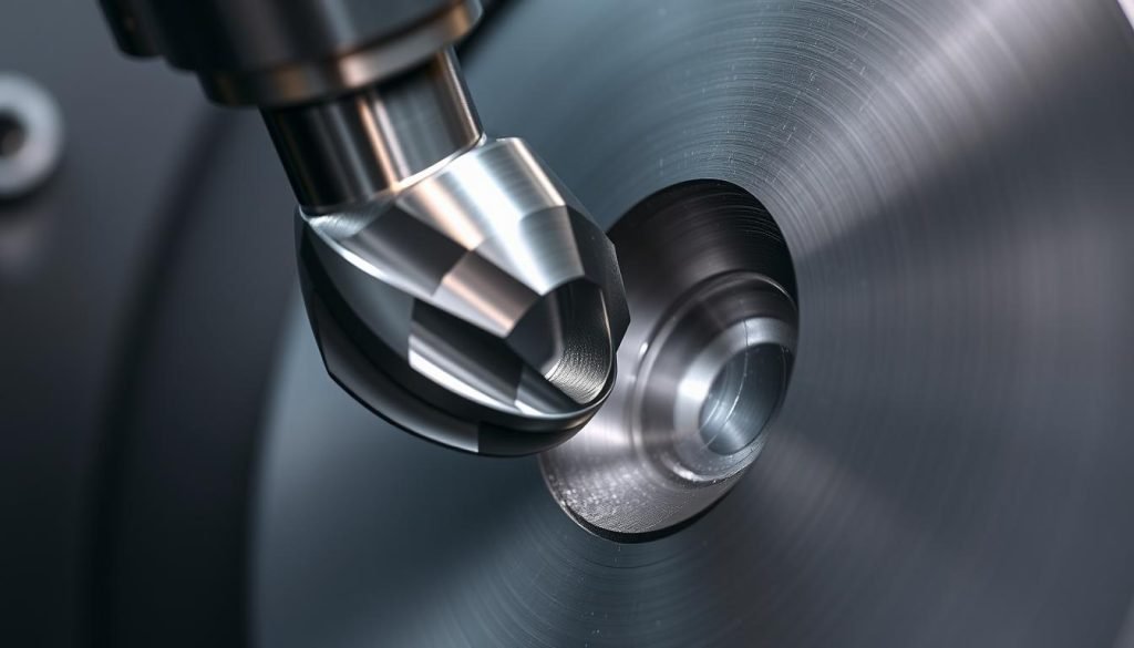
Interior fillets are used to round internal corners. They present unique manufacturing challenges, often requiring specialized tooling like ball end mills, which can impact production costs and timelines.
Exterior (Convex) Fillets
Exterior fillets smooth external edges, enhancing the product’s aesthetics and reducing the risk of damage from sharp corners.
Benefits of Using Fillets
The use of fillets provides superior stress distribution compared to other edge treatments, making them ideal for components subject to dynamic loading or fatigue. By reducing stress concentration, fillets enhance the overall durability and performance of parts.
What is a Chamfer?
When designing or manufacturing parts, understanding the nuances of edge treatments is crucial, and one common technique is creating a chamfer. A chamfer refers to a flat, sloped edge or corner, also known as a bevel, which is created by cutting away material at an angle.
Definition and Characteristics
A chamfer is a beveled edge that replaces a sharp corner or edge with a flat, angled surface. This edge treatment is typically created at an angle of 45 or 60 degrees. The characteristics of a chamfer include its ability to provide a clean, professional appearance while offering practical benefits.
Types of Chamfers
Chamfers come in various configurations, each suited to specific applications. The most common types include:
45-Degree Chamfers
45-degree chamfers are versatile and used for general applications. They are effective in deburring edges and facilitating assembly.
60-Degree Chamfers
60-degree chamfers are often used for screw holes and fastener interfaces. They serve as a lead-in for screws, allowing the head to sit flush with the part surface.
Benefits of Using Chamfers
Chamfers provide several benefits, including a clean appearance, deburring edges, and facilitating assembly. They also offer moderate stress relief and can be created with standard cutting tools, making them cost-effective. Additionally, chamfers excel in applications requiring lead-in features, such as guiding pins into holes or screws into threaded openings, thus improving assembly efficiency.
Technical Representation in Engineering Drawings
In engineering drawings, the representation of fillets and chamfers is crucial for accurate manufacturing. These features are essential in designs, impacting both the functionality and aesthetics of the final product.
How Fillets are Marked in Drawings
Fillets are typically dimensioned using the radius (R) value. For instance, “R3” indicates a fillet with a 3mm radius. This notation is standardized, making it clear to manufacturing teams how to execute the fillet feature correctly.
How Chamfers are Marked in Drawings
Chamfers are usually dimensioned using either the angle and length method or the unequal length method for asymmetrical chamfers. An example of the former is “2 x 45°,” indicating a 2mm length at a 45-degree angle. Understanding these notations is vital for the accurate production of parts with chamfered edges.
Different drawing standards, such as ASME or ISO, may have slight variations in representing these features. Modern CAD systems handle these representations through feature-based modeling, applying fillets and chamfers parametrically.
Manufacturing Processes for Fillets and Chamfers
To produce fillets and chamfers, manufacturers rely on advanced CNC machining tools and strategies. The choice of tooling and machining process significantly affects the quality and cost of the final product.
CNC Machining Tools for Fillets
CNC machining tools for fillets typically involve ball end mills or radius cutters. The diameter of the tool directly determines the minimum possible fillet radius that can be machined. For instance, an end mill tool with a diameter of 0.8 mm can create fillets with a radius as small as 0.4 mm.
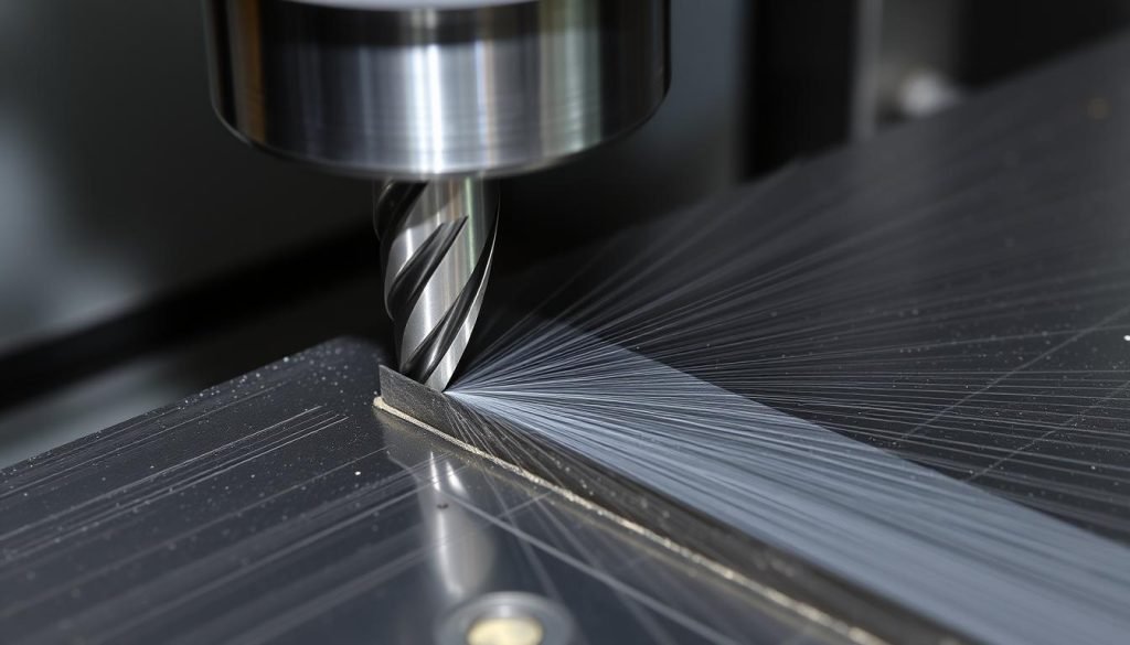
CNC Machining Tools for Chamfers
Chamfers are often produced using standard chamfer mills or angled end mills, which allow for faster material removal rates compared to fillet operations. The angle and size of the chamfer mill determine the characteristics of the chamfer.
Processing Challenges and Considerations
Manufacturing fillets and chamfers requires careful consideration of tool selection, machining strategies, and the challenges associated with creating these features. Interior fillets, for example, demand specialized ball end mills and often necessitate slower cutting speeds due to tool fragility.
The quality of the machined feature is directly related to the tool used and its wear over time. As tools wear, the consistency of fillets and chamfers across production runs can be affected, highlighting the need for regular tool maintenance and replacement.
Fillet vs Chamfer: The Core Differences
To make informed design decisions, it’s essential to grasp the core differences between fillets and chamfers. These differences are primarily categorized into geometric variations, stress distribution capabilities, and manufacturing complexities.
Geometric Differences
Fillets and chamfers differ fundamentally in their geometry. Fillets create a curved transition between two surfaces, while chamfers produce a linear, angled transition. This geometric difference significantly impacts the performance of the part.
Stress Distribution Capabilities
The curved surface of fillets allows for a more even distribution of stress, reducing stress concentration factors. In contrast, chamfers, with their sharp angles, tend to concentrate stress, making them less effective in high-load applications. Fillets can reduce stress concentration factors by up to 30-40% more effectively than chamfers.
Manufacturing Complexity Comparison
While fillets offer superior stress-handling capabilities, they are more complex and costly to manufacture. Chamfers, on the other hand, are simpler and more cost-effective to produce using standard tooling. The choice between fillets and chamfers often involves a trade-off between performance and manufacturing efficiency.
When to Use Fillets vs Chamfers
Choosing between fillets and chamfers depends on several factors, including the component’s functional requirements and manufacturing constraints. The right choice can significantly impact product performance, aesthetics, and production costs.
Ideal Applications for Fillets
Fillets are ideal for components subject to dynamic loading, fatigue, or stress concentration concerns. Examples include structural brackets, load-bearing shafts, and critical aerospace components. Using fillets in these applications helps to distribute stress more evenly, reducing the risk of material failure.
Ideal Applications for Chamfers
Chamfers excel in applications requiring assembly features, deburring of edges, or when manufacturing simplicity is prioritized over maximum stress reduction. For instance, a chamfer can serve as a lead-in for screws, making assembly easier and ensuring that the screw head sits flush with the component surface.
Industry-Specific Considerations
Different industries have unique requirements that influence the choice between fillets and chamfers. For example, in the automotive sector, fillets are often used in suspension parts to reduce stress concentrations, while chamfers are used for assembly interfaces to facilitate easier part assembly. Material selection also plays a crucial role, with brittle materials benefiting more from fillets’ stress-reduction properties. Additionally, the location of the feature on the part and production volume can impact the decision, with external visible edges sometimes favoring chamfers for aesthetic reasons and high-volume parts often opting for the simpler-to-manufacture chamfers to reduce unit costs.
Cost Optimization Strategies
Balancing functional requirements with manufacturing efficiency is key to optimizing costs for fillets and chamfers. Effective cost optimization strategies are crucial in modern manufacturing to minimize production expenses without compromising product quality.
Reducing Fillet Manufacturing Costs
To reduce fillet manufacturing costs, you can standardize fillet radii across your design, minimizing tool changes and specifying fillets only where functionally necessary. Using the largest acceptable fillet radius can also reduce machining time, as larger radii can be created with larger, more rigid tools that allow faster material removal rates.
Efficient Chamfer Implementation
Efficient chamfer implementation can significantly reduce production costs through standardization and the use of dedicated chamfering tools. Since a single tool can create chamfers of different sizes, incorporating chamfers into your design doesn’t necessarily increase manufacturing time or cost, making them a cost-effective option for edge treatments.
Conclusion: Making the Right Choice for Your Design
Understanding the implications of fillets and chamfers on your design is essential. The choice between these edge treatments depends on finding the right balance between functional performance, manufacturing feasibility, and cost considerations for your specific application.
You now know that fillets provide superior stress distribution but often at higher manufacturing complexity, while chamfers offer manufacturing efficiency with adequate edge treatment for many applications. By considering industry standards, material properties, and component function, you can make informed decisions about when each edge treatment is most appropriate.
Thoughtful edge treatment selection early in the design process can prevent costly modifications later and ensure your components perform as intended throughout their service life, optimizing the edges of your design.