")
What transforms a motor’s hidden spin into the force that drives our world? The answer is the electric motor shaft. This precision-ground steel component is the critical link, transmitting the rotor’s internal power outward to perform essential mechanical work. Far more than a simple component, its design and integrity are paramount. This guide will explore everything from its types and materials to key techniques for ensuring optimal performance.
What is an Electric Motor Shaft?
The electric motor shaft functions as the core rotating element within an electric motor assembly. This solid metal cylinder aligns perfectly along the motor’s center axis, extending beyond the motor casing at one or both ends. Inside the motor structure, it forms a rigid connection with the rotor – the component activated by electromagnetic forces when electrical power flows through the motor. Its fundamental purpose lies in physically bridging the internal electromagnetic actions of the motor with the external mechanical work required by driven equipment.
This component carries out the essential task of moving the rotational force generated inside the motor outward. Electromagnetic interactions produce torque within the rotor assembly. The shaft transfers this spinning force directly. Where it exits the motor casing, external couplings connect it to machines like industrial pumps, gear assemblies, conveyor belt systems, or fan blade rotors. Without the shaft pushing and pulling external components, the motor’s energy remains unusable outside its housing.
Beyond transmitting motion, the shaft serves as the foundational support structure for the rotor’s internal parts. Steel laminations that channel magnetic flux during operation stack along its length, locked in place through precise fits. Copper windings or permanent magnets mount firmly onto its surface. This transforms the shaft into the central column around which all rotor components organize and rotate as a unified mass. Any significant bending vibration or material failure disrupts this critical grouping.
Common Types of Electric Motor Shafts
Electric motor shafts represent the critical bridge between a motor’s internal spinning force and the external machinery requiring that motion. Different connection challenges require specific electric motor shaft types engineered for distinct operational demands. These variations directly impact how motors connect to loads and withstand diverse working conditions. Manufacturers produce several fundamental shaft configurations meeting industry requirements across applications.
Solid Shafts
Solid shafts stand as the universal foundation type encountered across countless motor installations. This design features a straightforward construction approach utilizing a single-diameter cylindrical bar manufactured with precision tolerances across its entire length. Simplicity drives this design – a solid bar provides predictable rigidity when subjected to rotating forces. Its consistent cross-section delivers reliable twisting resistance, making it suitable for constant-speed applications without special connection requirements.
You find this shaft type prevalent where standard power transfer suffices, like pump motors, fan assemblies, conveyor systems, and various industrial equipment needing straightforward torque delivery.
Hollow Shafts
Certain specialized applications require hollow shafts incorporating axial bores along their central axis. These shafts function as tubular conduits while maintaining rotational integrity. The engineered internal cavity serves multiple practical functions within compact installations. Significant weight reduction becomes possible compared to solid equivalents, particularly advantageous in robotics assemblies where mass reduction improves responsiveness.
This hollow pathway enables cable routing through rotating assemblies, commonly used when sensors and encoders require internal wiring connections. The design also allows fluid transfer through certain hydraulic motors while providing space for secondary rotating elements needing passage through the motor centerline.
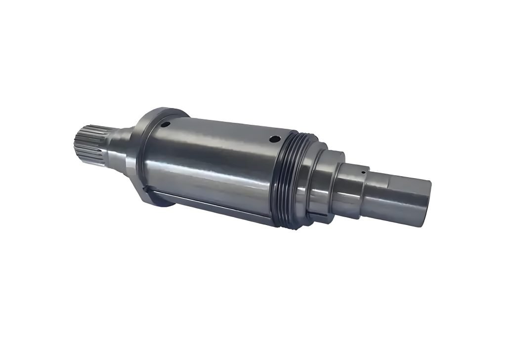
Stepped Shafts
Most practical motors rely on stepped shafts for internal assembly requirements despite their complex appearance. These shafts deliberately incorporate multiple diameter changes along their length to facilitate component mounting precision. Each section step serves dedicated mechanical functions critical to rotor assembly integrity. Larger diameter segments provide mounting surfaces for rotor laminations, stack retention through tight press fits, while smaller journal sections align precisely with bearing inner races, ensuring frictionless rotation support.
Additional steps house spacer elements, seal running surfaces, and external connection interfaces. This design remains essential for managing rotor compression loads while enabling precision bearing installation alignment within standard motor housings.
Tapered Shafts
Transferring substantial rotational forces to external equipment demands tapered shafts featuring conical connection surfaces. The gradually reducing diameter design enables exceptional mechanical locking through friction-based principles. Components like large flywheels, industrial pulleys, or crusher equipment mounted onto the taper become mechanically wedged against slippage under extreme loads. Split locking collars further secure components against torsional forces that could overcome friction.
This connection method excels in environments experiencing impact shocks, vibration stresses, and fluctuating load conditions that might compromise standard connections. Mining equipment, construction machinery, and bulk material handling systems rely heavily on this secure transmission method.
Keyed Shafts
Keyed shafts represent a universal feature adaptation rather than a distinct shaft of electric motor architecture. This modification involves machining longitudinal slots onto shaft segments requiring component retention. Rectangular keyways milled into solid, stepped, or tapered shafts provide engagement surfaces for square metal keys that simultaneously engage mating hubs. These small keys perform the critical task of torsionally locking external parts onto the shaft.
Preventing rotational slippage becomes essential at startup torque peaks or overload conditions affecting coupled equipment. This approach represents the industrial norm for connecting motors to drives across pumping stations, manufacturing machinery, generator couplings, and processing equipment. The method’s cost-effectiveness, standardization, and mechanical reliability ensure continued dominance despite alternatives like splines or specialized couplings existing.
Every motor shaft configuration ultimately provides the necessary physical interface allowing motors to transform electrical energy into valuable mechanical work across countless engineered systems globally. Understanding these fundamental variations empowers better motor selection for specific application requirements.
Common Materials for Manufacturing Motor Shafts
| Material | Key Properties | Typical Uses |
| Carbon Steel | Low cost, easy machining, good strength, needs rust protection | Factory motors, water pumps, air fans, and home appliances |
| Stainless Steel | Resists water damage, stays clean, and is hard to machine | Food machines, boat motors, and hospital equipment |
| Alloy Steel | Very strong, handles impacts, heat treatable | Heavy machines, rock crushers, power tools |
| Titanium | Light but strong, no rust, very expensive | Airplane parts, military gear, deep ocean motors |
| Aluminum | Very lightweight, bends easily, good heat flow | Robot arms, drone motors, and handheld tools |
- Carbon Steel: Most common choice for regular motors
- Stainless Steel: Required for wet/chemical locations
- Alloy Steel: Used when motors face strong impacts
- Titanium: Only for special jobs due to high cost
- Aluminum: Chosen when reducing weight is critical
Mill-Turn Machining Techniques for Motor Shaft Manufacturing
Modern motor shafts require high precision. Traditional machining methods often fall short. Mill-turn CNC machining solves this challenge. This advanced technique combines turning and milling operations. It happens on a single machine platform. Complex motor shaft geometries become achievable.
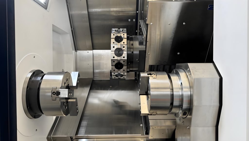
How Mill-Turn Works?
A mill-turn machine rotates the workpiece like a lathe. Cutting tools then approach from multiple angles. This allows turning cylindrical surfaces. Simultaneously, milling tools cut flats or keyways. Drilling holes happens in the same setup. Complex shapes like stepped profiles get machined accurately. Tapers and threads form precisely. All operations are complete without unclamping the part. This eliminates alignment errors between steps. Concentricity improves significantly.
Benefits of Mill-Turn Machining in Motor Shaft Production
Motor shafts demand exceptionally tight tolerances, perfect roundness on bearing journals, and exact keyway positioning. Mill-turn technology is ideal for achieving this precision. It streamlines production by machining complex features—from intricate hollow interiors to smooth stepped transitions—in a single setup. This not only ensures superior surface finishes for critical bearing contact but also significantly reduces production time, minimizes setup changes, and lowers material waste through highly efficient processing. The result is dramatically improved consistency across entire production batches.
Relationship Between CNC Mill-Turn and Motor Shaft
As the demand for smaller, more powerful motors grows, it drives the need for increasingly complex shaft designs with tighter tolerances. CNC mill-turn technology rises to meet these demands, capable of machining intricate features with unparalleled reliability.
Simultaneously, advancements in CNC technology—such as higher spindle speeds and more sophisticated live tooling—enable the creation of previously impossible shaft geometries. These superior shafts, in turn, are fundamental to building the next generation of high-efficiency, high-power-density motors. This creates a continuous feedback loop: evolving motor requirements push CNC development further, and enhanced CNC capabilities enable breakthrough motor performance.
This symbiotic cycle is precisely where Fecision’s powerful mill-turn capabilities deliver critical manufacturing advantages.
- Fecision’s Powerful Mill-Turn Capabilities
Fecision’s mill-turn technique is a formidable solution for manufacturing high-performance electric motor shafts. This approach is paramount for achieving the exceptional concentricity and geometric accuracy required by critical components like bearing journals and commutator fits. By utilizing advanced multi-axis mill-turn centers, Fecision ensures that all features—from precision-turned diameters and complex tapered sections to meticulously milled keyways and splines—are produced with perfect alignment, virtually eliminating the cumulative errors of traditional multi-step processing. This results in a superior, vibration-free shaft that delivers reliable power transmission and enhances overall motor efficiency and lifespan.
Furthermore, their expertise in handling a diverse range of materials, from robust carbon steels to challenging stainless alloys, ensures that every shaft is engineered to meet exact specifications for strength, durability, and performance.
Conclusion
In essence, the electric motor shaft stands as the vital mechanical link, transforming the rotor’s hidden spin into tangible power that drives our world. Its design—whether solid, hollow, stepped, or keyed—and material, from robust steels to specialized alloys, must be meticulously matched to its demanding role. As this guide has shown, achieving the precision, strength, and reliability required is no small feat. It is here that advanced CNC mill-turn machining proves indispensable, enabling the exacting tolerances and flawless concentricity that ensure these critical components perform seamlessly. Ultimately, the shaft’s integrity guarantees the motor’s purpose: delivering motion, power, and progress.