

Injection molding is a demanding yet vital manufacturing method for large-scale production, and the injection molding lifter plays a critical role in its efficiency. The lifter slides during the ejection stroke to pull cavity steel away from mold undercuts, enabling the production of complex geometries and undercuts in parts. This lifter mechanism in injection molding boosts efficiency, especially in high-volume manufacturing, by creating complex parts in a single cycle and ensuring quality that meets design needs.
This guide dives into what lifters are, how they work, their different types, a detailed injection mold lifter design walk-through, and how they compare to slides. By the end, you’ll have a solid grasp of how these parts can streamline your injection molding projects.
What Is an Injection Molding Lifter?
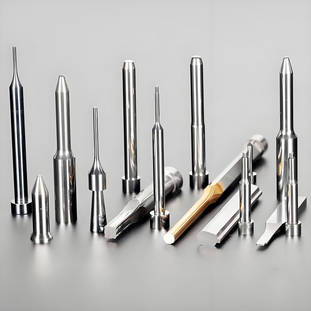
An injection molding lifter (or ejector pin) is a mold component that moves at an angle during ejection. It frees parts from undercuts or complex features that would otherwise trap them. It both releases undercuts and aids part ejection, ensuring clean removal and reducing damage risks.
Lifters improve efficiency by enabling complex geometries in a single cycle. Their simple, rigid design consists of a body and forming section, classified as integral (more compact, stronger, better for larger parts and easier combined use/maintenance) or non-integral. This makes them essential for intricate, high-quality production.
Injection Molding Lifter Working Principle
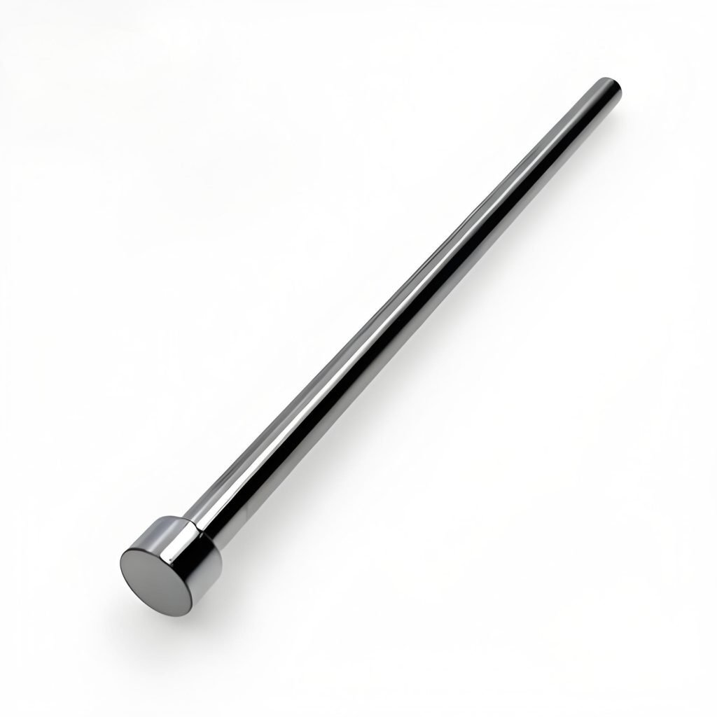
Injection molding lifters have a lifting part, usually a blade or pin, fixed to an ejector plate. Linked to this plate is a hydraulic or pneumatic system that governs its motion, and once the mold begins to open, the ejector plate, along with the lifter secured to it, starts to move upward, thereby pushing the plastic part out of the mold cavity.
The lifter goes into the cavity through a carefully drilled hole, pushing the piece up at an angle. The angle of the lifter is made to fit the part’s inner undercut, making sure the piece comes out evenly and smoothly. Sometimes, an ejector pin is used to add extra pushing power, so the part doesn’t get stuck on the lifter.
Types of Injection Molding Lifters (Integral Lifters/Non-Integral Lifters)
Lifters in injection molding generally fall into two categories: integral and non-integral.
Integral Lifters
The design features of an integral lifter mechanism lie in its high level of integration, combining the core ejection function components with necessary installation and fixing hardware into an inseparable unit. This integrated structure makes it particularly prominent in applications for small-sized, high-precision parts, as it effectively saves mold space and ensures precise coordination of actions. Additionally, due to its simple construction, the integral lifter mechanism is more convenient to operate during installation and debugging stages, and the maintenance workload and complexity required later on are relatively lower.
Non-Integral Lifters
Non-integrated lifters adopt a modular design concept, and their structure is clearly divided into two independently operating parts: one is the functional mechanism itself responsible for performing the ejection action, and the other is the matching, independent mounting and fixing components. This separate structure gives it higher design freedom and adaptability.
When facing large injection molded parts, non-integrated lifters are often the better choice because they need to overcome greater demolding resistance (i.e., higher ejection force). Its significant advantage is that it can be flexibly configured and customized according to the specific layout of the mold, space constraints, and specific ejection force requirements, so as to meet the specific requirements of complex or large molds.
The Detailed 9-Step Design Guide (Effective Tips)
Here is a comprehensive guide to designing injection mold lifters:
Step 1: Analyze the Part Design
The first step in designing an injection mold lifter is analyzing the part design thoroughly. You must examine its geometry – undercuts, holes, or other complex features that necessitate a lifter, along with required tolerances like dimensional accuracy. Also, consider material traits such as stiffness and shrinkage, as they influence the lifter’s design and function significantly.
Step 2: Determine the Lifter Position and Direction
The key steps in designing an injection mold lifter involve determining its position and direction. This requires a comprehensive consideration of part geometric features such as undercuts and complex structures, the location of the mold parting line, and the coordination with other components, including ejector pins, gates, runners, and venting systems, etc. The position refers to the fixed point on the mold, while the direction pertains to the angle of movement. Both factors jointly influence the smooth ejection of the part.
Engineers must select the optimal position and direction based on part design, mold structure, and ejection requirements, ensuring that it avoids interference from adjacent components while achieving efficient ejection.
Step 3: Design the Lifter Mechanism
Getting the lifter mechanism right is key for smooth part ejection. You’ve got a few main types to pick from: cam, hydraulic, and mechanical. Each works differently and fits different jobs.
- Cam mechanism is pretty straightforward – they turn a spinning motion into a straight lift. Great for simple jobs where you need good control without breaking the bank.
- Hydraulic mechanism is the muscles. They use hydraulic cylinders packing serious force, perfect when you’re dealing with heavy or complicated parts, and they’re flexible with different setups.
- Mechanical mechanism goes the linkage route, using springs or other mechanical means to get the lifting done. They’re reliable and offer some clever movement options.
Selecting the right lifter mechanism depends on multiple factors: part size and complexity, required force and speed, and mold space constraints. For example, cams suit simpler, low-force needs, while hydraulics excel with heavy loads. Mechanical options offer balanced performance for varied movements. Analyze the advantages and limitations of each mechanism type. This analysis helps pick the one that best fits your unique design requirements.
Step 4: Determine the Lifter Size and Shape
Proceed to define the injection mold lifter’s size and Shape, critical factors for its performance. These are determined by specific part geometry (including undercuts and complex features), the mold’s parting line and cavity layout, and the ejection system. To calculate the correct size, consider the part’s dimensions, required stroke length, and available mold space. The lifter’s shape must provide adequate support and stability throughout molding, accommodating part features without interfering with the process.
Step 5: Design the Lifter Support Structure
The lifter support structure stabilizes the lifter inside the mold. Its design depends on the mold layout, lifter size, and shape. Below are the key steps for designing this vital component:
Identify the Necessary Support
Before designing the support structure, engineers must identify where the lifter needs support. This includes areas experiencing high stress or force, or where it contacts the mold. Assessing these critical sections determines the necessary type and amount of support required.
Determine the Material
Choose a material for the support structure that suits the lifter design and injection molding process. It must withstand the forces and stresses encountered during operation, while also being compatible with the mold material itself.
Determine the Placement of the Support Structure
Now pinpoint exactly where to place the support structure within the mold. This location depends heavily on your specific lifter design and molding process requirements. Crucially, the supports must provide firm reinforcement precisely where needed, while avoiding interference with the mold or other components during operation.
Design the Support Structure
Design the lifter’s support structure to handle operational forces and stresses. It must be robust, and can be either a standalone part attached to the mold or integrated directly into the lifter itself.
Step 6: Analyze the Lifter Design
Engineers must thoroughly analyze the designed lifter mechanism and its support structure. This involves examining how the part’s complex features and potential undercuts influence the lifter’s size, shape, and movement. It’s critical to ensure the lifter integrates properly with the mold construction and interacts correctly with other components during ejection. The analysis must also determine the required structural strength to withstand operational forces without deforming, guaranteeing effective part release.
Step 7: Make Modifications to the Lifter Design
This step refines the lifter design based on prior analysis, optimizing performance and resolving identified issues. The process involves several critical actions:
Identify the Issue
Engineers must first pinpoint the exact problem with the lifter design through thorough analysis of test results or design reviews. Critically, discovering the root cause is essential to ensure modifications effectively solve the problem.
Evaluate Potential Solutions
Brainstorming solutions with experts and considering prior designs or best practices follows. Each solution needs careful evaluation for feasibility, cost, implementation ease, and expected impact on the lifter’s performance and mold integration, potentially requiring further analysis.
Implement Modifications
Selecting the best solution leads to implementation, which might involve changing the lifter’s geometry, material, or manufacturing process. Close attention to documenting these changes and updating all affected drawings is crucial.
Test the Modified Design
Rigorous testing using the original methods then verifies the modified design resolves the initial issue and performs as intended during ejection, initiating further iteration if necessary.
Step 8: Produce the Lifter
The finalized lifter design now moves into production. Key manufacturing methods include: machining, casting, or 3D printing.
- Machining shapes parts by cutting material, great for precise, small-batch components with tight tolerances.
- Casting pours melted material into molds to set, perfect for high-volume, complex shapes and cost-effective.
- 3D printing builds parts layer by layer from digital models, ideal for super complex designs with little tooling.
Material Selection
Pick materials with high strength and durability to handle ejection forces and stress. Also consider wear resistance, corrosion resistance, and the ability to withstand injection molding temperature changes to prevent degradation.
Step 9: Test the Lifter
This stage involves verifying the lifter functions correctly and identifying potential issues before production. Key methods include the following:
Moldflow Simulation
Used early in design, moldflow software simulates the lifter’s movement during injection molding. It spots problems like awkward movement, potential part defects, or interference with other mold components.
Prototype Molding
Building a prototype mold with the designed lifter helps check its movement, fit, and performance. It lets professionals evaluate part quality and functionality using a small batch of parts.
Test Molding
Using a test mold to produce more parts reveals issues missed in prototyping, such as excessive lifter wear or part stress. This method is especially useful for high-volume production setups.
Injection Molding Lifter vs Slide
In injection molding, both sliders and lifters are specialized mechanisms used to handle undercuts and ensure smooth part ejection, but they differ greatly in structure, function, and use. Understanding the main differences about injection molding lifter vs slide is crucial:
Sliders, often driven by angled pins or cam systems, move horizontally (or at an angle) to release external or side undercuts like side holes or overhangs. Lifters, typically actuated by the ejector plate, combine vertical and angular movement to tackle internal undercuts such as internal threads or clips. Their designs, costs, and operational constraints also vary significantly.
Comparison table as follows:
| Feature | Slider | Lifter |
| Primary Function | External undercuts (side holes, overhangs) | Internal undercuts (threads, clips, hooks) |
| Movement Direction | Horizontal or angled | Vertical with angular component |
| Actuation | Angled pin/cam system on mold opening | Ejector plate on mold opening |
| Key Trait | Clears outer surface obstructions | Clears inner surface obstructions |
| Complexity | Higher (needs guides, alignment) | Lower (needs angle precision) |
| Cost | Generally higher | Generally lower |
| Space Needs | Requires significant side space | Integrated into core, less footprint |
Start Your Injection Molding Project with Fecision
Need a dependable partner for your injection molding project? Fecision delivers high-quality services, expertly handling all aspects including complex injection mold lifter design.
Their team masters lifter in injection molding—whether your parts have simple undercuts or intricate geometries requiring advanced solutions. From complex lifter design to mass production optimization, Fecision ensures:
- Tight tolerances (as precise as ±0.001 in. / 0.025 mm)
- Superior dimensional stability for consistent part quality
- Fast cycle times (15–60 seconds per part) and high output (1,000+ parts/hour)
- Minimal material waste (<5%) with support for recyclable plastics (PET, PP, ABS, and 200+ material options)
- Cost-effective production with low per-unit costs at scale
- Durable tooling (millions of cycles) and smooth finishes (Ra 0.4–1.6μm)
Fecision guides you from initial injection mold lifter design analysis right through to final production. Choose them for your next project because they focus on quality, efficiency, and making sure you’re satisfied. Count on Fecision for precise, professional handling of your lifter in mold needs, resulting in high-quality parts that match your specs.
Feel free to contact Fecision to unlock the full potential of your mold design anytime.


