

Ever wondered how massive industrial networks maintain leak-free connections under extreme pressure? The answer lies in a simple yet vital component most people overlook.
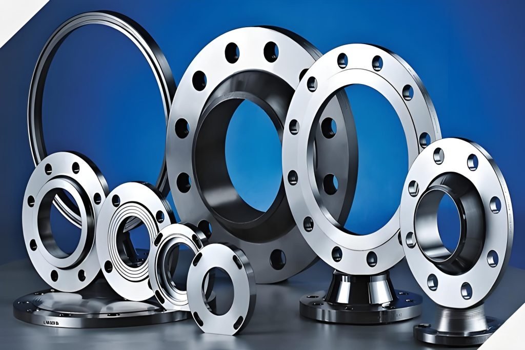
Flanges act as the backbone of secure pipeline connections. These flat, circular metal rings use strategically placed bolt holes to join pipes, valves, or equipment. Unlike permanent welds, they allow easy disassembly for repairs or upgrades—saving time and resources in critical systems.
Constructed with precision, each unit features a flange seat for alignment and a plate for structural integrity. Proper selection ensures tight seals under high temperatures or corrosive environments. Choosing the wrong type risks leaks, safety hazards, or costly downtime.
From oil refineries to water treatment plants, these connectors prove indispensable. Their design adheres to strict industry standards, balancing durability with adaptability. Understanding their role helps optimize performance across countless applications.
Ready to explore how different flange types solve unique engineering challenges? Let’s break down their designs, materials, and installation best practices.
Introduction to Flanges
From ancient aqueducts to modern refineries, connecting pipes has always demanded reliability. Precision components like lap joint flanges and weld neck flanges now enable industries to maintain secure, adaptable systems under extreme conditions. Their evolution mirrors technological progress—simple bolted joints of the 19th century have become engineered solutions for today’s high-stakes environments.
Overview of Flange Functions in Piping Systems
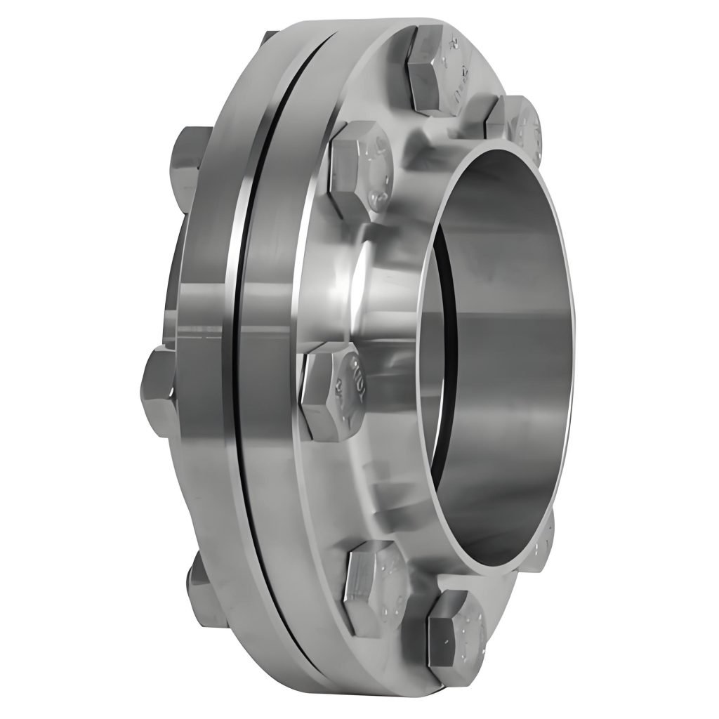
These connectors create leak-free seals while allowing modular assembly. Lap joint flanges excel in systems requiring frequent disassembly, sliding over pipes without welded attachments. Weld neck flanges, by contrast, provide reinforced joints for high-pressure pipelines. Both types prioritize safety and efficiency, adhering to strict operational standards.
What is a flange: Understanding Its Purpose and Role
Industrial systems depend on precision connections to maintain flow integrity under stress. These components bridge pipes and equipment through three primary methods: bolted, welded, or threaded joints. Each approach leverages unique design features to prevent leaks while accommodating maintenance needs.
Facilitating Connections and Sealing Performance
Bolted joints use gaskets compressed between aligned surfaces, creating seals that withstand vibration. Weld neck flanges provide reinforced joints for high-pressure systems, while threaded versions simplify assembly in tight spaces. Proper alignment ensures uniform stress distribution across the mating surfaces.
Materials like stainless steel or carbon alloys determine corrosion resistance and temperature tolerance. For example, chemical processing plants often use nickel alloys to handle aggressive substances. These choices directly impact long-term reliability and maintenance cycles.
Advantages for Pipeline Efficiency and Safety
Modular designs allow quick part replacements without dismantling entire sections. This reduces downtime during repairs—critical in power generation or oil refining. Flanges provide standardized interfaces, ensuring compatibility across equipment from different manufacturers.
Regular inspections of bolt tension and gasket condition prevent catastrophic failures. Selecting the right combination of materials and connection types optimizes both safety and operational costs.
Common Types of Flanges and Their Characteristics
Selecting the right connector can make or break industrial operations. Five primary designs dominate modern systems, each engineered for specific pressure levels and maintenance needs.
Slip-On, Weld Neck, Threaded, and Lap Joint Flanges
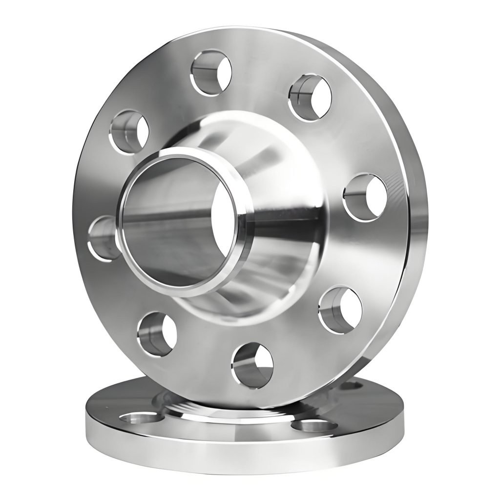
Slip-on versions slide over pipes for quick installation in low-pressure water systems. Their loose fit allows thermal expansion but requires double welding for stability. Weld neck units feature tapered hubs that reduce stress in oil pipelines handling 900+ PSI.
Threaded connectors screw onto pipes without welding—ideal for compressed air lines in tight spaces. Lap joint types pair with stub ends, enabling easy rotation during bolt alignment. These excel in food processing plants needing frequent cleanouts.
Material Selection and Industry-Specific Applications
Carbon steel handles moderate temperatures in power plants, while stainless variants resist acids in chemical processing. Alloy steel blends thrive in offshore drilling rigs facing saltwater corrosion.
Matching materials to operational demands prevents leaks and extends service life. Nuclear plants often choose nickel alloys for radiation resistance, whereas wastewater plants opt for epoxy-coated cast iron.
How Does Flange Connection Work?
Industrial networks rely on robust connection methods to maintain system integrity under varying pressures. Three primary techniques dominate modern installations—each offering unique benefits for specific scenarios.
Bolted, Welded, and Threaded Connection Methods
Bolted joints remain the most common choice for piping systems. Workers align two units with a gasket between them, then tighten bolts evenly to compress the seal. This method allows disassembly for maintenance but requires precise torque calibration.
Welded connections fuse components permanently, ideal for high-pressure environments like steam lines. Skilled technicians use arc welding to create seamless joints, eliminating potential leak points. However, this approach complicates future modifications.
Threaded flanges screw directly onto pipes without welding, perfect for compressed air or low-risk systems. Their simplicity speeds up installations in tight spaces but limits pressure tolerance compared to welded alternatives.
Ensuring Secure and Leak-Free Joints
Gaskets play a critical role in sealing performance. Materials like rubber or graphite fill microscopic gaps between surfaces, adapting to temperature changes.
Pressure requirements often dictate connection choices. Offshore platforms favor welded joints for saltwater resistance, while chemical plants use bolted designs with corrosion-resistant coatings. Proper alignment and standardized bolt patterns ensure uniform stress distribution.
Regular inspections detect issues like bolt loosening or gasket degradation. Following ASME installation guidelines minimizes risks, keeping systems operational for decades without failures.
Different Faces of a Flange to Connect
Pipeline systems rely on precise surface designs to maintain seals under stress. The shape of a flange’s contact area determines how effectively gaskets compress, adapt to pressure shifts, and prevent leaks. Four primary configurations dominate industrial applications.
Flat Face vs Raised Face Designs
Flat face flanges have smooth, even surfaces ideal for low-pressure water systems. They pair with full-face gaskets that distribute stress uniformly. Raised face designs feature a 1/16″ to 1/4″ elevated ring, concentrating compression on narrower gaskets. This boosts sealing in high-temperature oil pipelines.
Specialized Solutions for Extreme Conditions
Tongue and groove designs interlock like puzzle pieces, preventing gasket blowouts in chemical processing plants. Ring joint faces use oval or octagonal metal gaskets in recessed grooves—common in offshore drilling rigs handling 15,000+ PSI.
Selecting the right profile ensures leak-free operation while reducing maintenance costs. High-pressure steam lines often use raised face necks, while flat variants suit chilled water networks. Matching design to operational demands prevents costly failures.
Flange Dimensions and Sizing Considerations
Precision in measurement separates functional systems from hazardous failures. Proper sizing ensures components align perfectly with pipes and withstand operational pressure. Even minor errors can lead to leaks, joint stress, or catastrophic blowouts.
Key Measurements: OD, BCD, and Bolt Hole Details
Start with the outside diameter (OD)—the flange’s total width. This determines compatibility with pipe ends and gasket coverage. Next, measure the bolt circle diameter (BCD), the distance between opposing bolt holes. Industry standards like ASME B16.5 specify exact BCD tolerances for pressure classes.
Bolt hole count and diameter vary by application. A 4-hole pattern suits low-pressure water lines, while 16-bolt configurations handle extreme conditions. Always verify hole alignment using a bolt circle template.
Techniques for Accurate Flange Sizing
Use digital calipers for OD measurements and a micrometer for bolt hole diameters. For BCD, divide the distance between adjacent holes by the sine of 180 divided by the number of bolts. Cross-check results against ASME or DIN dimension charts.
Match components to pipe specifications, considering thermal expansion and vibration. High-pressure systems demand tighter tolerances than standard water lines. Regular calibration of measurement tools prevents costly installation errors.
Flange Classification, Service Ratings, Standards and Machining Process
Global engineering demands components that perform consistently across borders. Manufacturers classify connectors through pressure-temperature ratings and material grades, ensuring interoperability in complex systems. Compliance with international standards becomes the universal language of reliability.
Industry Standards and Markings
ASME B16.5 defines pressure classes from 150 to 2500 PSI for North American pipelines. DIN EN 1092-1 governs European systems, while JIS B2220 ensures compatibility in Asian markets. Stamped markings reveal critical data—”A182 F316″ indicates stainless steel alloyed with molybdenum for chemical resistance.
Certification logos like API Monogram or CE Mark validate testing protocols.
Machining Techniques
Closed-die forging aligns steel grain structures for high-pressure applications. Casting suits complex shapes in water systems but requires post-machining for precision. CNC lathes achieve ±0.001″ tolerances on bolt circles using carbide tooling.
Heat treatment optimizes material properties—quenching carbon steel enhances hardness. Surface grinding ensures flatness below 0.0005″ for leak-free seals. Proper equipment calibration maintains consistency across production runs.
Understanding these processes helps you select components matching operational demands. Rigorous quality checks—ultrasonic testing for voids or spectrometer alloy verification—prevent field failures. Choose certified partners to ensure system integrity.
Conclusion
Reliable pipeline networks form the circulatory system of modern industry. These connectors enable secure joins between pipes and equipment while allowing modular assembly. From weld neck designs handling extreme pressures to slip-on variants simplifying maintenance, each type serves distinct industrial applications.
Proper sizing—measuring OD, BCD, and bolt patterns—ensures leak-free performance. Standards like ASME B16.5 govern manufacturing tolerances, while material choices dictate corrosion resistance. Rigorous machining processes produce components that withstand decades of operational stress.
Your selection impacts entire systems’ longevity. Prioritize certified suppliers offering tested products. Matching specifications to project demands prevents failures and optimizes flow efficiency across piping systems.
When chosen wisely, these unassuming components become pillars of infrastructure reliability. Whether upgrading existing systems or designing new networks, informed decisions ensure seamless operation in critical industrial applications.


