

Plastic products are ubiquitous in modern life, from kitchens to workplaces. These items are primarily made through injection molding, where ejector pins play a critical role in automating production. Yet not all pins perform equally well. This article explores ejector pin fundamentals, different types, and how to optimize their design for more efficient injection molding processes.
What Are Injection Molding Ejector Pins?
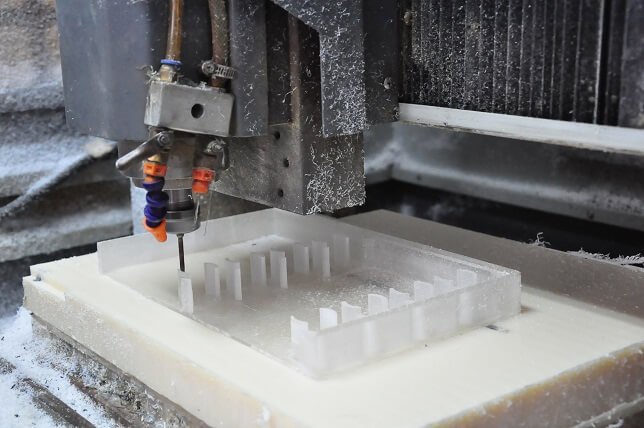
Ejector pins are crucial components in injection molding, directly impacting the quality of finished products. These pins function within a system that injects molten plastic into a two-part metal mold (comprising an A side and B side) where the material cools and solidifies into the desired shape. When the mold opens, the A side retracts while the B side holds the formed component, which is then ejected by the pins.
Selecting appropriate materials for ejector pins significantly affects their performance, durability, and the mold’s overall efficiency. Various materials are commonly used for these pins, each offering distinct advantages for different molding applications.
| Material | Tensile Strength (MPa) | Key Benefits |
| Stainless Steel (420, 440C) | 1900-2000 | Strength & Corrosion Resistance |
| Tool Steel (H13) | 1500 | Abrasion resistance and toughness |
| High-Speed Steel (M2) | 3900 | Extreme abrasion resistance |
Common Types of Ejector Pins
There are several types of pin ejectors used in the production of manufacturing. Here are the common types that you will find ideal for the injection molding process.
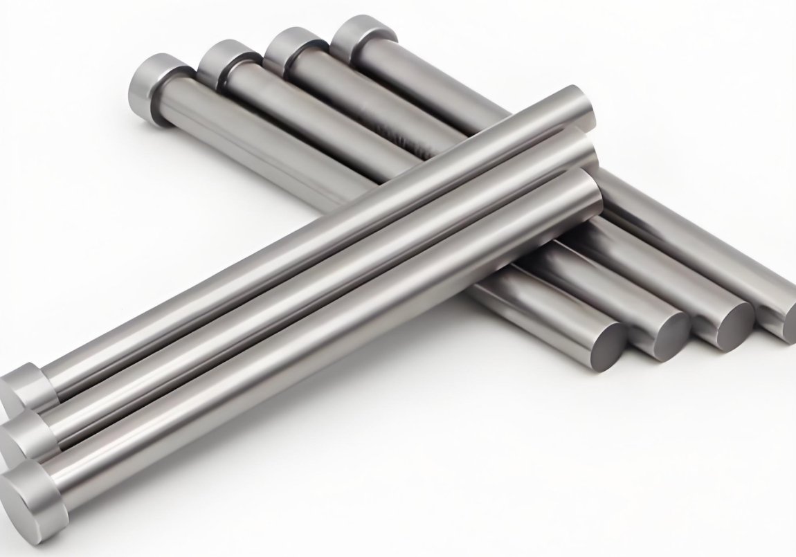
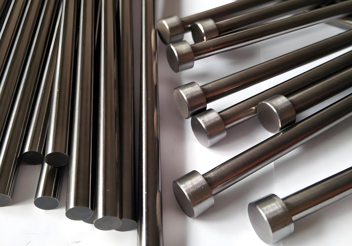
- Through-Hard Ejector Pins
These ejector pins undergo heat treatment to ensure consistent diameter and hardness. Through-hardened injection mold ejector pins can withstand temperatures up to 200°C, making them ideal for plastic ejection systems in molds.
- Case Hardened Ejector Pins
These are all classified as Nitride H13 pins, which are significantly harder than standard hard pins. They are suitable for both die casting and injection molding applications. The case-hardened ejector pins undergo nitrocarburization to achieve 65-70 HRC hardness and can withstand temperatures up to 200°C.
- Black Ejector Pins
Nitride H13 pins cannot operate at temperatures of 600℃. Manufacturers are currently developing advanced black ejector pins that feature a specialized surface coating. This black treatment provides self-lubricating properties, enabling the pins to withstand temperatures exceeding 1000℃. While these pins represent a more expensive solution, they are particularly suitable for metal injection systems in automotive molds.
- Ejector Sleeves
Ejector sleeves, also known as hollow pins, are used to produce mold parts with deep cores. These components are manufactured from hardened steel, ensuring precise ejection while minimizing part deformation. The hollow design of ejector sleeves accommodates internal cooling systems or allows for the integration of additional mechanisms.
- Ejector Plates
Ejector plates serve to secure and align multiple ejector pins to steel plates, ensuring even force distribution for smooth and precise ejection. This design is particularly suitable for complex molds.
- Ejector Blocks
Ejector blocks are the stable support for reinforcing ejector plates and pins and preventing misalignment. They are made of hardened steel, adding rigidity for high precision and heavy molds, ensuring stable ejection and longer mold life.
Design Principles for Ejector Pins & Ejector Systems
While mold suppliers can source ejector pins from external vendors, proper design considerations remain critical. Ejector pin design significantly impacts mold functionality by preventing part sticking and damage. Below are key design principles for ejection systems:
- Optimize the arrangement of core pin locations to improve the efficiency of mold design
When designing a mold, careful attention must be given to ejector pin placement. Optimal positioning typically occurs near binding areas or locations requiring high ejection force. Proper force distribution at critical points ensures smooth, precise part ejection while preventing damage or deformation. Strategically placing ejector pins in the mold design enhances ejection performance and increases overall injection molding success rates.
- Maintaining Clearance
To ensure proper operation and prevent interference, maintain a minimum clearance of 3.5mm between water lines and ejector pins. This spacing prevents collisions while allowing sufficient room for mold components. By adhering to this specification, the mold design facilitates smooth injection, effective ejection, and unimpeded cooling system functionality throughout the plastic injection molding process.
- Make sure it’s aligned correctly
To ensure proper mold operation and structural integrity, ejector pins must be positioned so they do not pass through holes in the ejection plate when approaching support columns. This alignment principle maintains correct ejection positioning and prevents plate movement. By following this guideline, the mold operates smoothly, enabling efficient part ejection while avoiding potential malfunctions or defects.
- Optimize the mounting orientation of the ejector pins to improve performance
To optimize ejector performance and durability, position pins horizontally while avoiding R-corners, acute angles, steep slopes, and gate proximity. Proper placement in smooth areas enables stable, efficient ejection force application, preventing potential damage to both mold and components. This design enhances overall functionality and reliability, ensuring smooth ejection while improving product quality.
- Ensuring Stability
When the ejector cup engages with the ejector pin, it should incorporate anti-rotation protection. This design prevents accidental cup rotation, ensuring precise alignment with the ejector pins. The anti-rotation mechanism allows the cup to withstand rotational forces while maintaining its intended orientation, reducing operational errors and preventing mold damage.
Common Defects and Solutions
If you do not follow the above ejector pin design, you may encounter the following defects:
- Ejector Pin Breaks
Ejector pin breakage typically results from excessive force rather than misalignment, material fatigue, or improper use. When the applied force exceeds the pin’s capacity or isn’t properly aligned with bending stress requirements, failure occurs. To resolve this issue, consider upgrading to through-hardened treatments or high-strength alloy materials, which offer superior durability.
- Ejector Pin Marks
Ejector pin marks always appear as flaws or depressions on the mold surface. These defects are caused by incorrect height of the pin (too long extension), excessive top-out force, or insufficient cooling, resulting in the pin sticking in the mold. In order to reduce this mark, it should polish the tip of the thimble smooth to create a smoother contact surface, and adjust its length to ensure the proper level position.
- Jetting
When the melted plastic flows into the mold inside too fast will appear the jetting, resulting in a flow. The ejector would appear on the waveform. The defects are caused by high injection speed and wrong location, and ejection damage. To reduce the jetting, it can lower the injection speed to make the layer flow or reposition the gate to make the material distribution place properly.
For more precise control, the adoption of the hot runner system can ensure the consistency of melt temperature and flow, thereby minimizing the defects related to flow to the greatest extent.
How to Choose the Right Ejector Pins in Injection Molding?
To choose the right pin, you have to consider the material, size, etc. Here’s an explanation of these factors and others you may need to keep an eye on during the injection molding cycle.
- Choose a Large Ejector Pin Diameter
Generally speaking, if you use a large ejector pin, this will be best for a large molded part, as a large diameter will reduce the penetration of the needle into the molded part by reducing the penetrating force. Also, you should make sure that the diameter is an integer (avoid decimals and non-standard values).
- Ejector Pin Size
While the pins should have a large diameter, they should also have a correspondingly small size. The adjustment should depend on the size of the molded part. Reducing the size of the ejector pin will reduce penetration into the molded part.
- Strength Requirement
The pin should be strong enough to withstand high injection pressures. Make sure the pin diameter is 2.5mm or greater to avoid pin bending. If not, you should use a shoulder thimble. In addition, you should make sure that the strength can counteract the weakening in injection molding.
Final Words
A well-engineered ejector pin is critical to achieving flawless injection molding results. It ensures:
✔ High-quality production – Minimizes surface defects (e.g., pin marks, sticking, or deformation)
✔ Cost efficiency – Reduces downtime, mold damage, and rejected parts
✔ Optimal ejection – Maintains precision in complex geometries
However, designing and implementing the perfect ejector system requires expertise. That’s where Fecision excels.
Final Words
Deep Technical Knowledge – Our team specializes in ejector pin optimization for defect-free molding.
✔ Custom Solutions – We design pins tailored to your mold’s requirements (material, cooling, ejection force).
✔ End-to-End Support – From design to production, we ensure seamless integration into your process.
✔ Need expert guidance? Fecision guarantees:
- Pin mark reduction – Smoother ejection, better surface finish
- Durability – High-strength materials for long-lasting performance
- Efficiency – Faster cycles, lower maintenance costs
Don’t compromise on quality—contact Fecision today! Our support team is ready to assist with custom ejector pins injection molding solutions for your needs.


