

Did you know that nearly 90% of modern engineering analysis relies on the Finite Element Method (FEM) to simulate and predict the behavior of complex systems? This numerical technique has revolutionized the field of engineering by enabling the detailed analysis of structural, fluid, and thermal dynamics.
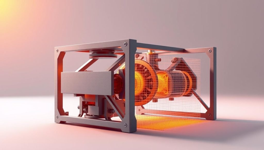
FEM is crucial for engineers who need to design and analyze complex machining parts. By breaking down a system into smaller elements, FEM allows for the precise calculation of stresses, strains, and other physical phenomena. This not only optimizes product performance but also significantly reduces the need for physical prototyping, saving time and resources.
As we explore the basics and applications of FEM, you’ll gain insights into how this powerful tool can enhance your engineering analysis capabilities.
What is the Finite Element Method?
To grasp the significance of FEM, it’s essential to understand its definition and core principles. The Finite Element Method is a computational technique used to solve partial differential equations that describe the behavior of complex systems. You can apply FEM to various engineering disciplines, including structural mechanics, thermal analysis, and fluid dynamics.
Definition and Core Principles
The Finite Element Method is based on dividing a complex problem into smaller, simpler problems that can be solved individually. This is achieved by discretizing the domain of interest into smaller elements, called finite elements, which are connected at nodes. The core principle of FEM lies in its ability to approximate the solution to a problem by using simple functions, known as shape functions, to interpolate the solution within each element.
You can analyze the behavior of each element separately and then assemble the results to obtain the global solution. This approach allows for the efficient analysis of complex systems, making FEM a powerful tool in engineering analysis.
The Mathematical Foundation of Finite Element Method
The mathematical foundation of the finite element method is rooted in partial differential equations and variational principles. This foundation is crucial for understanding how the finite element method solves complex problems in various fields of engineering.
Partial Differential Equations in FEM
Partial differential equations (PDEs) play a significant role in the finite element method. They are used to describe the physical behavior of systems under various conditions. The finite element method discretizes these PDEs into a system of algebraic equations that can be solved numerically. This process involves dividing the problem domain into smaller elements, where the solution is approximated.
Variational Principles and Energy Minimization
The principle of minimization of energy forms the backbone of the finite element method. When a boundary condition is applied to a body, multiple configurations are possible, but the configuration that minimizes the total energy is the one that is realistically achieved. This principle is leveraged in the finite element method to find solutions to complex problems by approximating the configuration that minimizes the system’s total energy.
You will learn how physical systems tend toward configurations that minimize their total energy, and how the finite element method uses this principle to solve problems. The variational approaches transform differential equations into integral forms that are more amenable to numerical solution, making the finite element method particularly powerful for structural mechanics problems.
Basic Concepts and Terminology of FEM
To grasp the Finite Element Method (FEM) fully, it’s necessary to understand its basic terminology and concepts. The FEM is a numerical technique used to predict how structures or fluids behave under various conditions by breaking down complex problems into simpler, more manageable parts.
Elements, Nodes, and Meshes
In FEM, the domain of interest is divided into smaller parts called elements. These elements are connected at points known as nodes. The collection of elements and nodes forms a mesh, which represents the geometry of the problem. The type and number of elements used can significantly affect the accuracy of the analysis.
The mesh can be composed of various element types, such as triangular, quadrilateral, or hexahedral elements, depending on the problem’s dimensionality and complexity. The choice of element type and mesh density is critical for achieving accurate results.
Degrees of Freedom
Degrees of freedom (DOF) refer to the number of independent parameters required to specify the configuration of a system. In FEM, DOF is associated with the nodes and represents the possible displacements or other variables at those points. Understanding DOF is crucial for setting up the correct boundary conditions and interpreting the results.
Shape Functions and Interpolation
Shape functions, also known as interpolation functions, are used to approximate the variation of the field variables (such as displacement or temperature) within an element. These functions are defined based on the nodal values and enable the FEM to interpolate values at any point within the element. The mathematical formulation of shape functions ensures they satisfy properties like the partition of unity and local support, which are essential for the accuracy and stability of the FEM analysis.
By using shape functions, FEM can transform a continuous problem into a discrete system of equations, allowing for the approximation of solutions at any point in the domain based on the values calculated at discrete nodal points.
The FEM Workflow: Step-by-Step Process
To leverage the full potential of FEM, it’s essential to grasp the step-by-step process that underpins this analysis technique. The FEM workflow is a structured sequence of operations that transforms a complex engineering problem into a solvable numerical model, providing valuable insights into the behavior of the system under analysis.
Pre-Processing: Model Preparation
In the pre-processing stage, you prepare your model for analysis. This involves defining the geometry, material properties, and boundary conditions. You discretize the model into finite elements, creating a mesh that represents the complex system. The quality of the mesh significantly affects the accuracy of the analysis.
Processing: Solving the System
During the processing stage, the FEM software solves the numerical model. It assembles the element equations into a global system of equations and then solves for the unknowns, such as displacements or temperatures. This stage is computationally intensive and requires significant numerical processing power.
The solver uses various numerical methods to find the solution, ensuring that it satisfies the governing equations and boundary conditions. The output from this stage is a set of numerical results that describe the behavior of the system.
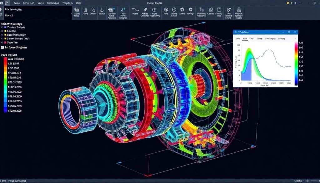
Post-Processing: Analyzing Results
In the post-processing stage, you interpret the results of the analysis. This involves visualizing the output data to understand the behavior of the system. You can use various visualization techniques, such as contour plots, vector displays, and deformation animations, to gain insights into the results.
It’s crucial to critically evaluate the results, verifying them against analytical solutions, convergence studies, and physical intuition. This ensures that the results are accurate and meaningful, providing a reliable basis for engineering decisions. Remember, the principle of “Garbage In equals Garbage Out” (GIGO) applies; the quality of the input directly affects the quality of the output.
Discretization: The “Divide and Conquer” Approach
In the finite element method, discretization involves dividing the solution domain into smaller subdomains, called finite elements. This process is crucial for transforming a continuous problem into a discrete model that can be analyzed computationally.
Mesh Generation Techniques
Mesh generation is a critical step in discretization, where the domain is subdivided into a mesh of elements. The choice of mesh generation technique depends on the geometry of the problem and the desired level of accuracy. Local mesh refinements are particularly useful for focusing on areas of high stress or interest, allowing for a more efficient use of computational resources.
Element Types and Selection
The selection of appropriate element types is vital for the accuracy and efficiency of the finite element analysis. Different types of elements (1D, 2D, 3D) are suited for various applications, and the choice between first-order and higher-order elements affects both solution accuracy and computational cost. For instance, higher-order elements can provide more accurate results but at a higher computational cost. Specialized elements, such as shell elements for thin structures and contact elements for interfaces, are used for specific applications.
When choosing element types, you must consider the geometry of your model, the expected behavior under load, and the computational constraints. By selecting the most appropriate element type and order, you can achieve a balance between accuracy and efficiency in your finite element analysis.
Boundary Conditions in Finite Element Analysis
Boundary conditions are essential in finite element analysis as they define the constraints and loads on a system. You need to understand how to apply these conditions to achieve accurate results. Boundary conditions can be broadly classified into two categories: geometric (essential) boundary conditions and force (natural) boundary conditions.
Geometric (Essential) Boundary Conditions
Geometric boundary conditions, also known as essential boundary conditions, are constraints that are applied to the displacements or deformations of a system. These conditions are typically related to the geometry of the problem and are used to define the support or fixation of a structure. For instance, in the analysis of a cantilever beam, the displacement at the fixed end is set to zero, which is an example of a geometric boundary condition. You must ensure that these conditions are applied correctly to prevent rigid body motion and to simulate the real behavior of the system.
Force (Natural) Boundary Conditions
Force boundary conditions, or natural boundary conditions, represent the external loads applied to a system, such as forces, pressures, or moments. These conditions are crucial in simulating the real-world loading scenarios that a component or structure might experience. For example, the load applied at the free end of a cantilever beam is a force boundary condition. You will learn how to apply various types of force boundary conditions, including concentrated forces, distributed loads, and time-dependent loads, to accurately model complex loading scenarios. The correct application of force boundary conditions is vital for obtaining accurate results in your finite element analysis.
Finite Element Analysis Capabilities
The capabilities of FEA software are vast, allowing for detailed analysis of static, dynamic, and modal behaviors. You can leverage these capabilities to analyze complex systems, optimize designs, and predict potential failures.
Static Analysis
Static analysis involves evaluating the response of a system to steady-state loads, providing insights into stress, strain, and deformation. This type of analysis is crucial for understanding how a structure or component will behave under constant loads, helping you to identify potential failure points and optimize the design.
Dynamic Analysis
Dynamic analysis, on the other hand, examines the behavior of a system under time-dependent loads, such as vibrations or impacts. By analyzing the dynamic response of a structure, you can predict how it will react to various dynamic conditions, ensuring that it can withstand the stresses imposed upon it.
Modal Analysis
Modal analysis is a critical tool for understanding the vibrational characteristics of a system. It determines the natural frequencies and mode shapes of a structure, providing essential information for vibration analysis and design. Through modal analysis, you can identify resonant frequencies where structures are susceptible to amplified vibration responses, potentially leading to failure.
Mode shapes reveal the patterns of deformation associated with each natural frequency, offering insights into structural behavior. The applications of modal analysis are diverse, including vibration control, noise reduction, fatigue analysis, and dynamic design optimization. Moreover, modal results serve as the foundation for more complex analyses, such as frequency response analysis, random vibration analysis, and dynamic transient analysis.
Advantages and Limitations of FEM

Understanding the benefits and drawbacks of FEM is crucial for effective application in various engineering fields. The Finite Element Method offers a powerful tool for analysis, but its successful implementation depends on recognizing both its advantages and limitations.
Key Benefits of Using FEM
The Finite Element Method provides several key benefits that make it a preferred choice for many engineering analyses. One of the primary advantages is its ability to provide detailed insights into the behavior of complex systems under various conditions. By breaking down a complex problem into smaller, more manageable elements, FEM enables engineers to obtain accurate solutions that would be difficult or impossible to achieve through traditional analytical methods. This capability is particularly valuable in the design and analysis process, where understanding the nuances of a system’s behavior is critical.
FEM also allows for the simulation of different scenarios and the analysis of how changes in design or conditions affect the overall performance of a system. This flexibility is a significant advantage in optimizing designs and ensuring that they meet the required specifications and performance criteria. Furthermore, the method’s ability to handle nonlinear problems and complex material behaviors makes it an indispensable tool in modern engineering analysis.
Challenges and Constraints
Despite its many advantages, FEM also has several challenges and constraints that engineers must be aware of. One of the primary limitations is the dependence of the solution accuracy on the quality and refinement of the mesh. A coarse or poorly constructed mesh can lead to inaccurate results, and ensuring mesh convergence can be a time-consuming process. Additionally, the computational demands of FEM, particularly for large and complex models or nonlinear analyses, can be significant, requiring substantial computational resources.
Another challenge is the potential for singularities or other numerical issues that can arise if the model is not properly constrained or if the boundary conditions are not correctly applied. Engineers must also be cautious of over-constraining the model or making inappropriate simplifications, as these can lead to misleading results. Understanding these challenges and being aware of the potential pitfalls is essential for the effective application of FEM in engineering analysis.
The Relationship Between FEA and FEM
Finite Element Analysis (FEA) is the practical application of the Finite Element Method (FEM), transforming theoretical foundations into real-world solutions. As you explore the capabilities of FEA software, you’ll find that it relies heavily on the mathematical principles outlined by FEM.
FEM as the Method, FEA as the Application
The Finite Element Method (FEM) is a numerical technique used to solve partial differential equations in various fields of engineering. On the other hand, Finite Element Analysis (FEA) is the application of FEM to real-world problems, utilizing software tools to perform the complex calculations required for analysis. You can think of FEM as the “how” and FEA as the “what” – the method versus its application.
How They Work Together in Practice
In practice, engineers use FEA software to analyze complex structures and systems. This software implements FEM algorithms, often shielding users from the underlying mathematical complexities. As you work with FEA tools, understanding the principles of FEM can enhance your ability to interpret results and make informed decisions. The interplay between FEM and FEA has evolved significantly with advances in computing power, making sophisticated analyses more accessible.
Applications of FEM in Materials Science
FEM has become a crucial tool in materials science, allowing researchers to simulate complex material behaviors and optimize material properties. This capability is particularly valuable for understanding how materials respond to various conditions.
Structural Analysis of Materials
Structural analysis using FEM enables the examination of material behavior under mechanical loads, helping to predict failure points and optimize structural integrity. This analysis is critical for designing materials that can withstand different types of stress.
Thermal and Fluid Analysis
FEM is also applied in thermal and fluid analysis to study the interaction between materials and their thermal and fluid environments. This includes analyzing heat transfer and fluid flow around or through materials, which is essential for applications involving high temperatures or fluid dynamics.
Multiphysics Applications
One of the most exciting prospects is the application of FEM in coupled problems, such as fluid-structure interaction, thermomechanical, thermochemical, and thermo-chemo-mechanical problems. These multiphysics simulations enable the study of complex material behaviors under various conditions, driving innovation in materials science.
By leveraging FEM for these advanced simulations, researchers can design and optimize materials with coupled functionalities and responses to multiple stimuli, advancing the field of materials science.
Advanced FEM Techniques and Developments
To improve the accuracy of finite element analysis, researchers are exploring advanced techniques. These developments are crucial for tackling complex engineering problems more effectively.
Extended and Generalized FEM
Extended and Generalized Finite Element Methods (FEM) offer enhanced capabilities for solving problems with complex geometries or discontinuities. These methods allow for a more accurate representation of the analysis domain by enriching the finite element space with special functions that capture the local behavior of the solution. This is particularly useful in fracture mechanics and other applications where traditional FEM may struggle to provide accurate results.
Adaptive Mesh Refinement
Adaptive mesh refinement is a technique used to automatically adjust the finite element mesh to improve the solution accuracy where needed. By refining the mesh in areas with high gradients or complex behavior, you can achieve a more accurate solution without unnecessarily increasing the computational cost. This involves using error estimation methods to identify regions requiring refinement, allowing you to focus computational resources where they provide the most benefit.
Different refinement strategies are employed, including h-refinement (subdividing elements into smaller elements), p-refinement (increasing the polynomial order of elements), and hp-refinement (combining both approaches). The hp-FEM, for instance, combines automatic mesh refinement with an increase in polynomial order, enabling each element to have different polynomial orders after refinement.
Conclusion
Mastering the Finite Element Method enhances your ability to innovate and improve engineering designs. By leveraging FEM, you can simulate various scenarios, predict potential failures, and optimize performance, all within a virtual environment. This not only streamlines the design process but also reduces the need for physical prototypes, saving time and resources.
In conclusion, the Finite Element Method is a fundamental tool in modern engineering, offering a robust framework for analyzing and optimizing complex systems. As you continue to work with FEM, you’ll find that its applications extend far beyond the examples discussed here, into various fields where complex problem-solving is critical.


